


3–29
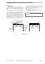
OPERATIONS AND TIMING
COPYRIGHT
©
1998 CANON INC. CANON NP6621 REV.0 FEB. 1998 PRINTED IN JAPAN (IMPRIME AU JAPON)
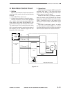
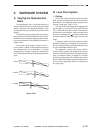
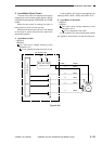
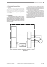
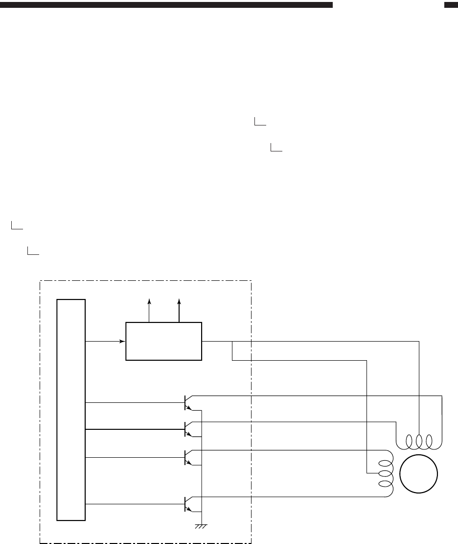
2. Lens Motor Drive Circuit
The lens motor (M3) is a stepping motor and is
rotated by the drive power supply signal LNSCA/
LNSCB and pulse signals LNSA/LNSA* and LNSB/
LNSB*.
When the lens motor is rotating, the motor is
being driven by 34 V to move the lens.
Whenever the lens motor is at rest, 5 V is applied
to the motor to ensure that the lens is kept at the
appropriate position.
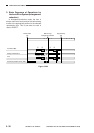
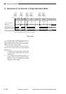
a. Lens Motor at Rest
• LNSCA=0
LNSCB=0
The motor drive voltage switching circuit
switches to 5 V.
5 V is supplied to keep the motor at rest.
In this condition, the motor is kept stationary by
keeping LNSA, LNSA*, LNSB, and LNSB* all ‘0’.
b. Lens Motor in Operation
• LNSCA=1
LNSCB=1
The motor driver voltage switching circuit
switches to 34 V.
34 V is supplied to the motor.
In this condition, the motor rotates when pulses
are applied to each phase in a specific sequence.
>
>
>
>
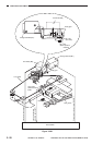
Figure 3-203
34V 5V
LNSCB
LNSCA
LNSA
LNSA*
LNSB
LNSB*
J 324B- 1
- 4
- 5
- 6
- 2
- 3
M3
DC controller PCB
Microprocessor
Motor drive voltage
switching circuit
Lens motor
(Q301)