


COPYRIGHT
©
1998 CANON INC. CANON NP6621 REV.0 FEB. 1998 PRINTED IN JAPAN (IMPRIME AU JAPON)
CHAPTER 4
MECHANICAL SYSTEM
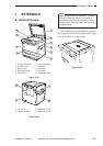
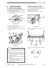
I. EXTERNALS ............................................. 4-1
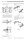
A. External Covers ................................... 4-1
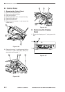
B. Control Panel ....................................... 4-2
C. Removing the Display Panel ............... 4-2
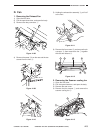
D. Fan ...................................................... 4-3
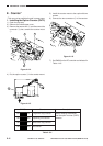
E. Counter ................................................ 4-4
II. DRIVE SYSTEM ........................................ 4-5
A. Scanner Drive System......................... 4-5
B. Lens Drive Assembly .........................4-10
C. Main Motor......................................... 4-14
III. PICK-UP/FEEDING SYSTEM ................. 4-15
A. Pick-Up Assembly ............................. 4-15
B. Multifeeder Assembly ........................ 4-17
C. Registration Roller Assembly ............ 4-20
D. Feeding Assembly ............................. 4-22
E. Delivery Assembly ............................. 4-22
F. Duplexing Assembly .......................... 4-23
G. Cassette Unit .....................................4-24
H. Paper Deck Pedestal-K1 ................... 4-27
IV. EXPOSURE SYSTEM ............................. 4-34
A. Illuminating Assembly........................ 4-34
V. CHARGING SYSTEM ............................. 4-38
A. Drum Unit .......................................... 4-38
B. Primary Charging Assembly .............. 4-39
C. Transfer Charging Assembly ............. 4-40
D. Drum Heater ...................................... 4-41
VI. DEVELOPING SYSTEM ......................... 4-42
VII. FIXING SYSTEM ..................................... 4-45
VIII
.ELECTRICAL........................................... 4-50
A. DC Controller PCB ............................ 4-50
B. Composite Power Supply PCB ......... 4-50
C. AE Sensor PCB ................................. 4-51
1.
Before disassembly or reassembly work, disconnect the heating (if a heater is installed)
and main body power cord(s).
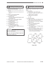
2. Group the screws by type (length and diameter) and location.
3. The fixing screw for the grounding wire and varistors is fitted with a washer to ensure
electric continuity; be sure to use the washer for reassembly.
4. If possible, avoid operating the machine with any of its parts removed.
5. Unless otherwise noted, reassembly is the reverse of disassembly.