


3–13
OPERATIONS AND TIMING
COPYRIGHT
©
1998 CANON INC. CANON NP6621 REV.0 FEB. 1998 PRINTED IN JAPAN (IMPRIME AU JAPON)
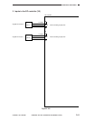
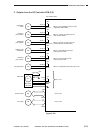
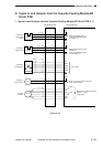
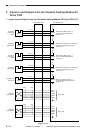
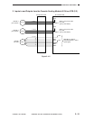
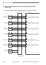
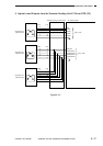
E. Inputs to and Outputs from the Cassette Feeding Module-B2
Driver PCB
1. Inputs to and Outputs from the Cassette Feeding Module-B2 Driver PCB (1/1)
Figure 3-113
5V
J 110- 1
- 3
- 2
J 110- 4
- 6
- 5
PS1cu
C3VPD
Cassette 3
vertical path
sensor
5V
PS2cu
C3PD
Cassette 3
paper sensor
When PS1 detects paper, '1'.
(when the light-blocking plate
is at PS1cu, '1')
When paper is present in the
cassette, '0'.
(when the light-blocking plate
is not at PS2cu, '0')
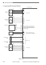
Cassette driver PCB
DC controller PCB
J 651
- 6
- 5
- 4
- 3
- 2
- 1
J 110
- 7
- 8
- 9
- 10
- 11
- 12
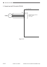
CS2
C2SZ1
C2SZ2
C2SZ3
C2SZ4
Cassette 3
size detection
See p. 3-85.
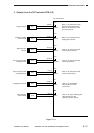
CMA
CMA*
CMB
CMB*
J 114- 1
- 2
- 3
- 4
- 5
- 6
Cassette
unit motor
While M1cu is rotating, alternates
between '1' and '0'.
(pulse signal)
M1cu
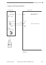
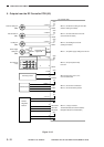
When '0', the pick-up clutch turns ON.
(pick-up roller rotates)
RGCLD*
CL1cu
+24V
+24V
+24V
J 115- 1
- 2
Cassette 3
pick-up clutch