THE INSTRUCTION SET
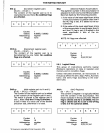
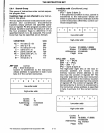
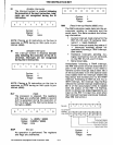
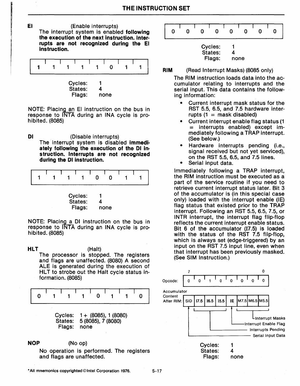
EI
(Enable interrupts)
The interrupt system is
enabled following
the execution
of
the next instruction. Inter·
rupts are not recognized during the
EI
instruction.
1
1 1
1
o
1 1
Cycles: 1
States: 4
Flags: none
NOTE:
Placin~
EI
instruction on the bus in
response to
INTA during
an
INA cycle is pro-
hibited.
(8085)
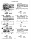
01
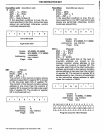
(Disable interrupts)
The interrupt system is
disabled immedi·
ately following
the execution
of
the
01
in·
struction. Interrupts are
not
recognized
during the
01
instruction.
1 1
1 1 o
o
1
1
Cycles: 1
States: 4
Flags: none
NOTE:
Placin~
01
instruction on the bus in
response to
INTA during
an
INA cycle is pro-
hibited. (8085)
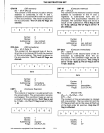
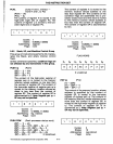
HLT (Halt)
The processor is stopped. The registers
and
flags are unaffected. (8080) A second
ALE is generated during the execution of
HL T
to
strobe out the Halt cycle status
in-
formation.
(8085)
o 1
NOP
1
o
1
Cycles: 1 +
(~m85),
1 (8080)
States: 5
(8085),
7 (8080)
Flags: none
(No op)
o
No operation is performed. The registers
and
flags are unaffected.
* All
mnemonics
copyrighted © Intel Corporation 1976.
5-17
o
o
o 0
o 0
o
o
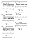
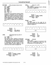
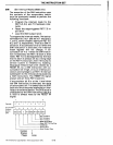
RIM
Cycles:
States:
Flags:
1
4
none
(Read
Interrupt Masks) (8085 only)
The
RIM
instruction loads data into the ac-
cumulator relating
to
interrupts and the
serial input. This data contains the follow-
ing information:
• Current interrupt mask status for the
RST
5.5, 6.5, and 7.5 hardware inter-
rupts
(1
= mask disabled)
•
Current interrupt enable flag status
(1
= interrupts enabled) except im-
mediately following
a TRAP interrupt.
(See
below.)
•
Hardware interrupts pending (i.e.,
signal received but not yet serviced),
on the
RST
5.5,6.5, and 7.5 lines.
• Serial
input data.
Immediately following a TRAP interrupt,
the
RIM
instruction must be executed as a
part
of
the service routine
if
you need
to
retrieve current interrupt status later. Bit 3
of the
accumulator is (in
this
special case
only) loaded with the interrupt enable
(IE)
flag status
that
existed prior
to
the TRAP
interrupt.
Following an
RST
5.5,6.5, 7.5, or
INTR interrupt, the interrupt flag flip-flop
reflects
the current interrupt enable status.
Bit 6
of
the accumulator
(17.5)
is loaded
with the status of the
RST
7.5 flip-flop,
which is always set (edge-triggered) by
an
input on the
RST
7.5
input line, even when
that interrupt has been
previously masked.
(See
SIM Instruction.)
7
0
Opcode:
I
0
0
0 0 0
0
I
Accumulator
Content
After
RIM:
Lnterru~t
Masks
Interrupt Enable Flag
Interrupts Pending
Serial
Input Data
Cycles:
1
States: 4
Flags:
none


