


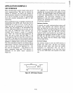
APPLICATION EXAMPLE 2
CRT
INTERFACE
Most microprocessor systems require some sort
of
serial communications. This may be selected for
reasons
of
economy
(to
reduce the number
of
interconnections required in a distributed system),
or
it may be necessary in order
to
communicate
with such common peripherals
as
CRT's
or
tele-
typewriters.
These
,peripherals
all
use a standard convention for
transmitting serial ASCII code. Each data byte
is
transmitted
as
a series
of
10
or
II
bits. The uni-
form time per bit corresponds
to
the data trans-
mission rate.
For
example,
if
the transmission rate
is
to
be 2400 baud (2400 bits per second), each bit
time must be
1/2400 bps = 416.7 J.lsec/bit. The
standard
IO-bit sequence consists
of
a logically
zero
"Start"
bit, 8 data bits (least significant bit
first), and one
or
more stop bits (logic I). An
II-bit
sequence with two stop bits
is
used for 110
baud TTY's. The logic one level continues until the
start
bit
of
the next byte
to
ensure
that
each 10-bit
sequence
is
initiated with a one-to-zero transition.
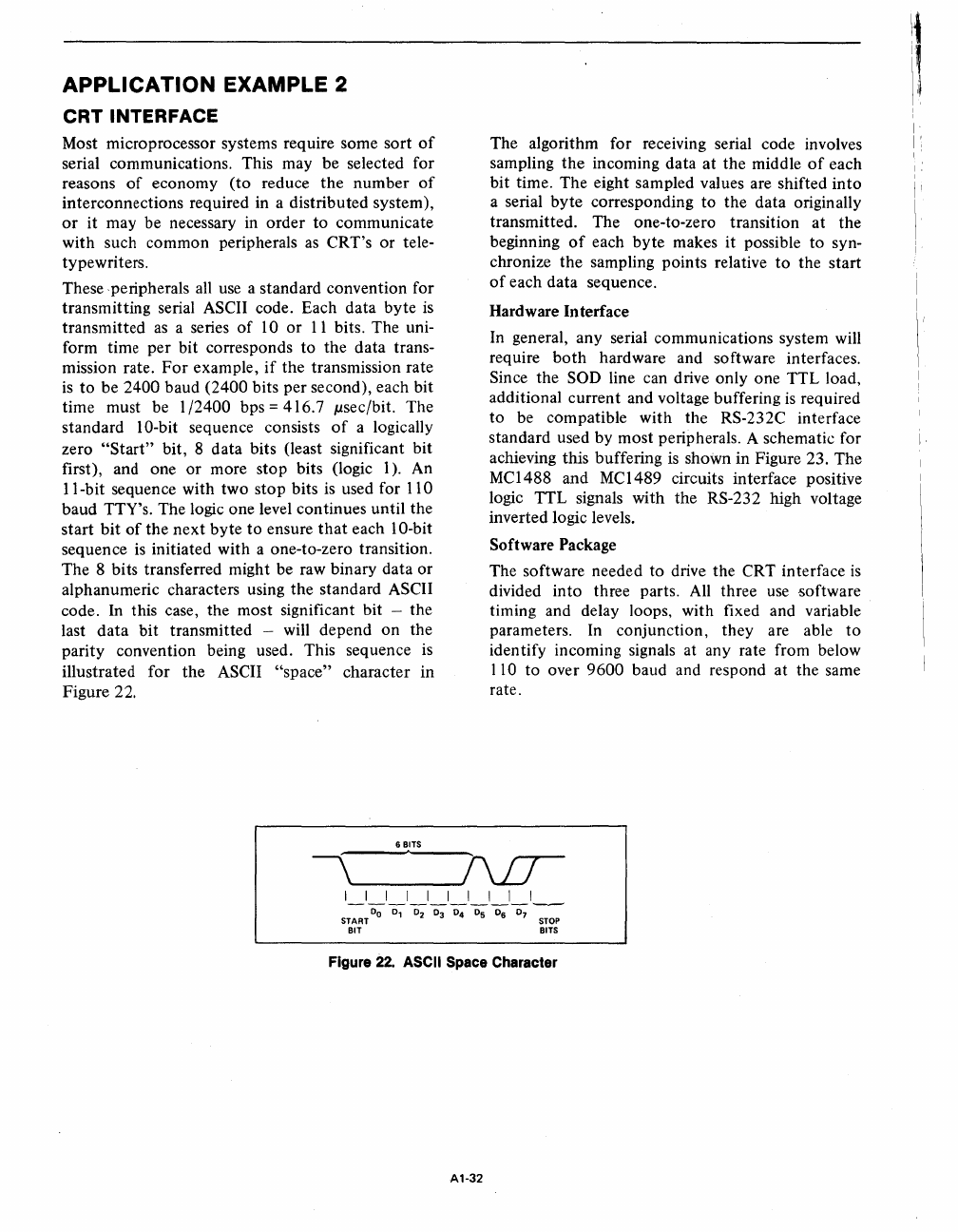
The 8 bits transferred might be raw binary data
or
alphanumeric characters using the standard ASCII
code.
In
this case, the most significant bit - the
last
data
bit transmitted - will depend
on
the
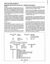
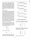
parity convention being used. This sequence
is
illustrated for the ASCII
"space"
character in
Figure 22.
6 BITS
The algorithm for receiving serial code involves
sampling the incoming data at the middle
of
each
bit time. The eight sampled values are shifted into
a serial
byte
corresponding to the data originally
transmitted. The one-to-zero transition at the
beginning
of
each
byte
makes it possible to syn-
chronize the sampling points relative
to
the start
of
each data sequence.
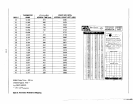
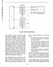
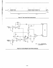
Hardware Interface
In general, any serial communications system will
require
both
hardware and software interfaces.
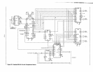
Since the
SOD line can drive only one TTL load,
additional current and voltage buffering
is
required
to
be compatible with the RS-232C interface
standard used by most peripherals. A schematic for
achieving this buffering
is
shown in Figure 23. The
MC1488 and MC1489 circuits interface positive
logic TTL signals with the RS-232 high voltage
inverted logic levels.
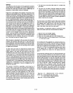
Software
Package
The software needed to drive the CRT interface
is
divided into three parts.
All
three
use
software
timing and delay loops, with fixed and variable
parameters. In conjunction, they are able
to
identify incoming signals at any rate from below
I
10
to
over 9600 baud and respond at the same
rate.
I I I I I I I I I I
5;':;0;
D,
0; 0;
0;
Os
0; 0;
:;
BIT BITS
Figure
22.
ASCII
Space
Character
A1-32
11,"
I"
Ii
I
I
I
I':
I'