Intel MCS-80/85 Computer Hardware User Manual


The
events
that
take
place
during
the
T3
state
are
determined
by
the
kind
of
machine
cycle
in progress. In a
FETCH
machine
cycle,
the
processor
interprets
the
data
on
its
data
bus
as
an
instruction.
During
a
MEMORY
READ
or
a
STACK
READ,
data
on
this
bus
is
interpreted
as a
data
word.
The
processor
outputs
data
on
this
bus
during
a
MEMORY
WRITE
machine
cycle.
During
I/O
operations,
the
processor
may
either
transmit
or
receive
data,
de-
pending
on
whether
an
OUTPUT
or
an
INPUT
operation
is
involved.
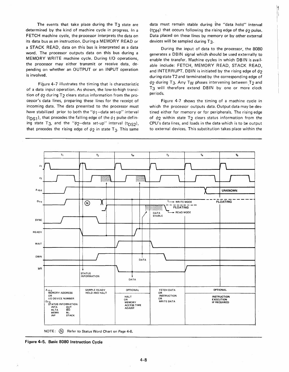
Figure
4-7
illustrates
the
timing
that
is
characteristic
of
a
data
input
operation.
As
shown,
the
low-to-high transi-
tion
of
¢2
during
T2
clears
status
information
from
the
pro-
cessor's
data
lines,
preparing
these
lines
for
the
receipt
of
incoming
data.
The
data
presented
to
the
processor
must
have
stabilized
prior
to
both
the
"¢1-data
set-up"
interval
(tDS1),
that
precedes
the
falling
edge
of
the
¢1
pulse
defin-
ing
state
T3,
and
the
"¢2-data
set-up"
interval
(tDS2),
that
precedes
the
rising
edge
of
¢2
in
state
T 3.
This
same
T,
T2
Tw
n
Irr\
n
LJ
\
--.l
~
I
-
@
X
data
must
remain
stable
during
the
"data
hold"
interval
(tDH)
that
occurs
following
the
rising
edge
of
the
¢2
pulse.
Data
placed
on
these
lines
by
memory
or
by
other
external
devices
will be
sampled
during
T3.
During
the
input
of
data
to
the
processor,
the
8080
generates
a DBIN signal
which
should
be
used
externally
to
enable
the
transfer.
Machine
cycles
in
which
DBIN
is
avail-
able
include:
FETCH,
MEMORY
READ,
STACK
READ,
and
INTERRUPT.
DBIN is
initiated
by
the
rising edge
of
1>2
during
state
T2
and
terminated
by
the
corresponding
edge
of
¢2
during
T3·
Any
TW
phases
intervening
between
.T2
and
T3
will
therefore
extend
DBIN
by
one
or
more
clock
periods.
Figure
4-7
shows
the
timing
of
a
machine
cycle
in
wh
ich
the
processor
outputs
data.
Output
data
may
be des-
tined
either
for
memory
or
for
peripherals.
The
rising
edge
of
1>2
within
state
T2
clears
status
information
from
the
CPU's
data
lines,
and
loads
in
the
data
which
is
to
be
output
to
external
devices.
This
substitution
takes
place
within
the
T3 T4
T5
n
n
h
J
L
W
l
W
L
'/..
UNKNOWN
------------
L-.
WRITE MODE
FLOATING
-
___
-t-
___
~
FLOATING
...J
L..-.
READ MODE
DATA
STABLE
SYNC
READY
1\
WAIT
1\
DBIN
DATA
WR
II
STATUS
INFORMATION
DATA
A'5·0
SAMPLE
READY
OPTIONAL FETCH
DATA
OPTIONAL
MEMORY ADDRESS
HOLD
AND
HALT
OR
OR
HALT
INSTRUCTION
INSTRUCTION
1/0 DEVICE NUMBER
OR
OR
EXECUTION
DH
MEMORY
WRITE
DATA
IF
REQUIRED
STATUS
INFORMATION
ACCESS
TIME
INTA
OUT
ADJUST
HLTA
W6
MEMR
M,
INP STACK
NOTE: ® Refer
to
Status
Word
Chart
on Page 4-6.
Figure
4-5.
Basic
8080
Instruction Cycle
4-8