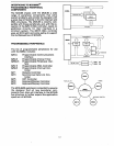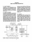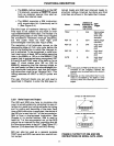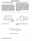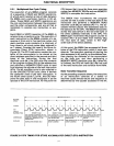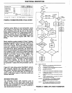
The 8085A's
CPU
registers are distinguished as
follows:
•
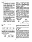
The accumulator (ACC or A Register) is
the focus
of
all
of
the accumulator in-
structions (Table
4-1),
which include
arithmetic, logic,
load and store, and I/O
instructions. It is
an
8-bit register only,
(However, see Flags, in
this
list.)
•
The program counter
(PC)
always points
to
the memory location
of
the next in-
struction
to
be executed. It always con-
tains a 16-bit address.
• General-purpose registers
BC,
DE,
and
HL
may
be
used as
six
8-bit registers or
as three 16-bit registers, interchangeably,
depending on the instruction being
per-
formed. HL functions as a data pointer to
reference memory addresses that are
either the sources or the destinations in
a number
of
instructions. A smaller
number
of
instructions can use
BC
or
DE
for
indirect addressing.
• The stack pointer
(SP)
is a special data
pointer that always points
to
the stack
top
(next available
stack
address). It is
an indivisible 16-bit register.
• The flag register contains five one-bit
flags, each
of
which records processor
status information and may
also control
processor
operation.
(See
following
paragraph.)
2.2.2
Flags
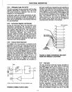
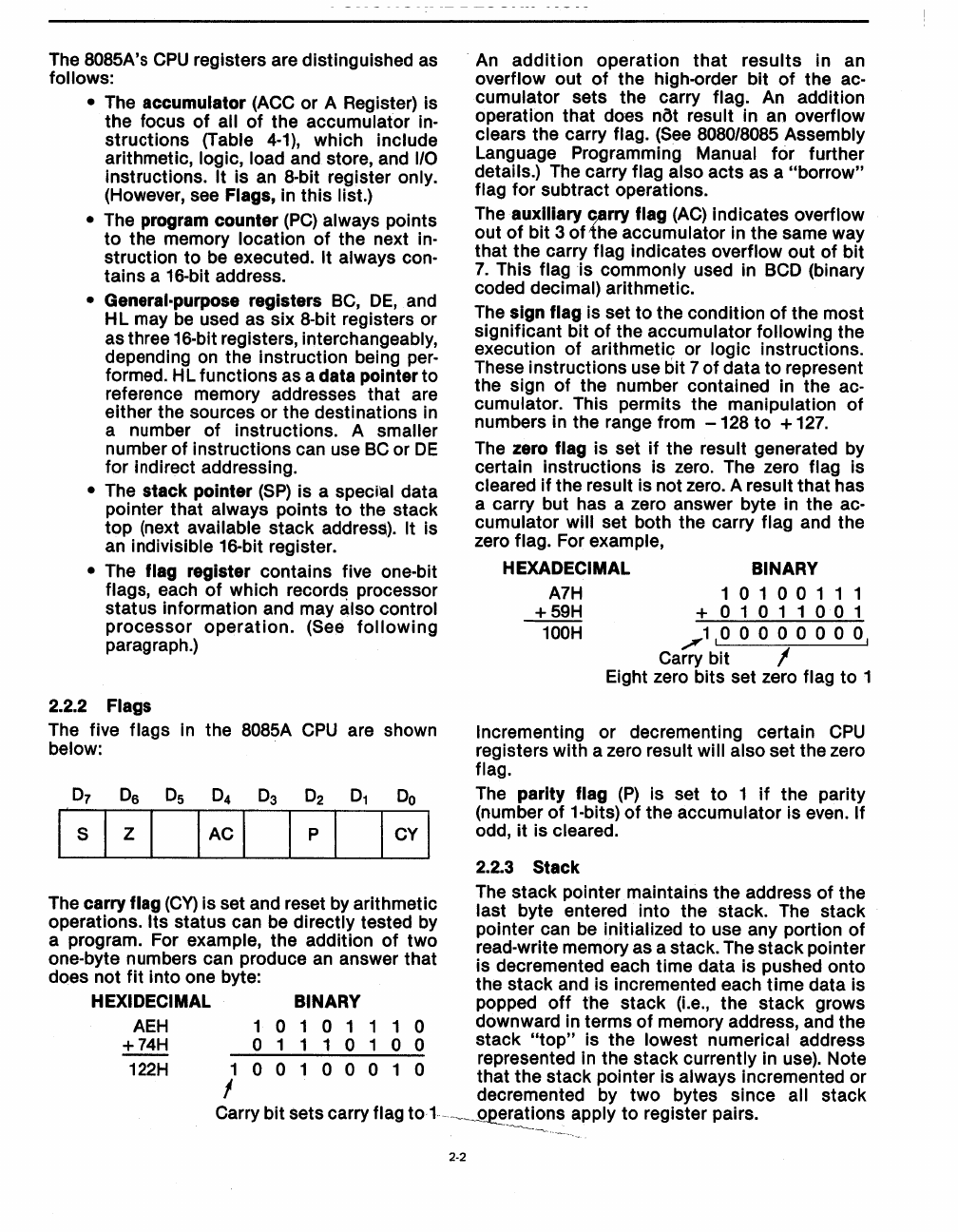
The five flags in the 8085A
CPU
are shown
below:
06
Is
z
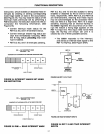
The carry flag (Cy) is set and reset by arithmetic
operations.
Its
status can be directly tested by
a program. For example, the addition
of
two
one-byte numbers can produce an answer that
does not
fit
into one byte:
HEXIDECIMAL BINARY
.
An
addition
operation
that
results
in an
overflow out
of
the high-order bit
of
the ac-
cumulator sets the carry flag. An addition
operation that does
not result in an overflow
clears the carry
flag.
(See
8080/8085 Assembly
Language Programming Manual
for
further
details.) The carry
flag also acts as a
"borrow"
flag
for
subtract operations.
The auxiliary
c~rry
flag
(AC)
indicates overflow
out
of
bit
3
of
-the
accumulator in the same way
that the carry
flag indicates overflow
out
of
bit
7.
This flag is commonly used in BCD (binary
coded decimal) arithmetic.
The sign
flag is set
to
the condition
of
the most
significant bit
of
the accumulator following the
execution
of
arithmetic or logic instructions.
These instructions use bit 7
of
data
to
represent
the sign
of
the number contained in the ac-
cumulator. This permits the manipulation
of
numbers in the range from
-128
to
+
127.
The zero flag is set
if
the result generated by
certain instructions is zero. The zero
flag is
cleared
if
the result is not zero. A result
that
has
a carry but has a zero answer byte in the
ac-
cumulator will set both the carry flag and the
zero
flag. For example,
HEXADECIMAL BINARY
A7H
+59H
100H
1010011
1
+01011001
~1,0
0 0 0 0
000,
Carry bit I
Eight zero bits set zero flag
to
1
Incrementing or decrementing certain
CPU
registers with a zero result will also set the zero
flag.
The parity flag
(P)
is set
to
1
if
the parity
(number
of
1-bits)
of
the accumulator is even. If
odd,
it
is cleared.
2.2.3 Stack
The
stack
pointer maintains the address
of
the
last byte entered into the stack. The stack
pointer can be initialized
to
use any portion
of
~ead-write
memory as a stack. The
stack
pointer
IS decremented each time data is pushed onto
the
stack
and is incremented each
time
data is
popped
off
the stack
(Le.,
the
stack
grows
AEH
+74H
1 0 1 0 1 1 1 0 downward in terms
of
memory address, and the
o 1 1 1 0 1 0 0 stack
"top"
is the lowest numerical address
1
0 0 1 0 0 0 1 0 represented in the stack currently in use). Note
I that the stack pointer is always incremented or
. decremented by
two
bytes since all stack
Carry
bit sets carry flag
to
1.-
..
~
__
~rations
apply
to
register pairs .
......
..-............_-...-,.,
122H
2-2


