1---------Tl--------~--------T2--------~--------T3--------1
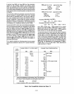
elK
OUT
ALE
ADDR8-15
STATUS
ADO·7
(READ MODE)
ADO·7
(WRITE MODE)
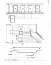
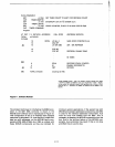
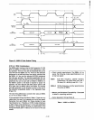
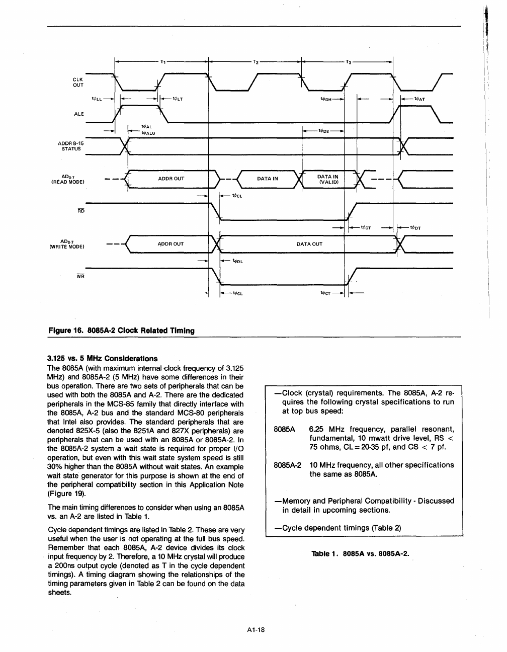
Figure 16. 8085A·2 Clock Related Timing
3.125
vs. 5
MHz
Considerations
The
SOB5A
(with maximum internal clock frequency of 3.125
MHz)
and
SOS5A-2
(5 MHz) have some differences
in
their
bus operation. There are two sets of peripherals that can be
used with both the
SOS5A
and A-2. There are the dedicated
peripherals
in
the MCS-S5 family that directly interface with
the S085A, A-2 bus and the standard
MCS-BO
peripherals
that Intel also provides. The standard peripherals that are
denoted B25X-5 (also the
S251A
and B27X peripherals) are
peripherals that can be used with an
SOS5A
or
SOS5A-2.
In
the B085A-2 system a wait state is required for proper I/O
operation, but even with this wait state system speed is still
30% higher than the
BOS5A
without wait states. An example
wait state generator for this purpose is shown at the end of
the peripheral compatibility section
in
this Application Note
(Figure
19).
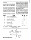
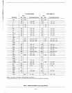
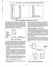
The main timing differences to consider when using
an
SOB5A
vs. an A-2 are listed
in
Table
1.
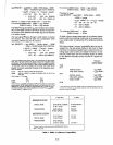
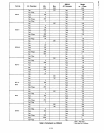
Cycle dependent timings are listed in
Table
2.
These are very
useful when the user is not operating at the full bus speed.
Remember that each
SOS5A,
A-2 device divides its clock
input frequency by
2.
Therefore, a
10
MHz crystal will produce
a 200ns output cycle (denoted as T
in
the cycle dependent
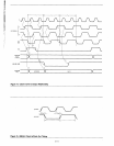
timings). A timing diagram showing the relationships of the
timing parameters given
in
Table 2 can be found
on
the data
sheets.
A1-18
-Clock
(crystal) requirements. The
BOS5A,
A-2
re-
quires
the
following
crystal
specifications
to
run
at
top
bus speed:
8085A
6.25 MHz frequency, parallel resonant,
fundamental, 10
mwatt
drive level,
RS
<
75
ohms,
CL=20·35
pf, and CS < 7 pf.
8085A-2 10 MHz frequency, all
other
specifications
the
same as 8085A.
-Memory
and Peripheral
Compatibility
- Discussed
in detail in upcoming sections.
-Cycle
dependent
timings
(Table
2)
Table
1.
8085A VS. 8085A-2.
i!l"I."
I',
I
I'
II,
!I
I'


