1
1
',
,I
,
,
t
t
i
t
sion rates,
as
computed
for
the
selected crystal
freq uency. Initialization would req uire the oper-
ator
to
hit
a specific
key
several times (usually the
"U"
key, which generates a
pattern
of
alternating
ones and zeros). The identification routine would
attempt
to
"read"
this
pattern
at
each baud rate,
in
turn,
until finding
the
rate at which the read
was successful.
The cassette recorder used to develop the tape
interface was a Lloyd's push-button model which
cost $17 in 1972. Empirical testing has indicated
that
for this application, the quality
of
the cassette
recorder
is
less critical than
the
quality
of
the
tape
itself. In
other
words, some
33~
cassettes were
not
very reliable, even when used with more expensive
recorders.
When using a cassette at the beginning
of
a side,
allow
the
tape to run for
about
10 seconds until
the
leader has passed before starting
to
write data.
Otherwise, data will be lost
to
the leader.
Depending
on
the
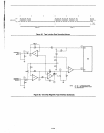
recorder quality, the tone
burst
freq uency and
duration
can be optimized for
higher
data
rates
by
modifying HALFCYC and
CYCNO. If so, CKRATE should also be reduced,
so
that
between
about
10 and
80
data samplings
are made during a single (one-third width)
tone
burst. At greatly increased frequencies, some
of
the
A1·43
components
in
the
analog interface might also be
modified.
The two simple routines for recording
and
playing
back blocks
of
data
were intended
to
illustrate
one
way
of
using TAPEIN and TAPEO, and therefore
do
not
contain any provisions for
error
detection
or
correction. Depending on the nature
of
a partic-
ular application, these routines could be aug-
mented with parity bit or checksum comparison,
or
an
error
correcting code technique.
Funny
things happen when recording and playing
back a page
of
RAM which includes
the
subroutine
stack. Eventually, PLA YBK will
start
writing over
the
data at
the
top
of
the stack, destroying
the
subroutine traceback sequence. The
next
RET
instruction will then cause a
jump
to
a place where
you'd
rather
not
be.
The
printout
reproduced
in
the
CRT
Code inchides
the
assembled listings for
the
CRT
and magnetic
tape interfaces discussed
in
this application
note.
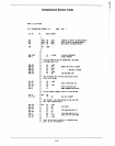
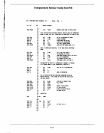
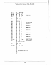
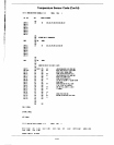
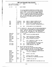
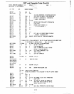
The object code produced was programmed
into
an 8755 EPROM, which was installed in the expan-
sion
PROM socket
of
the SDK-85 board. Some
very minor differences exist between this listing
and the code segments presented earlier, which
were written for
maximum
clarity.


