


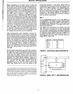
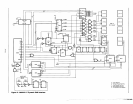
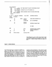
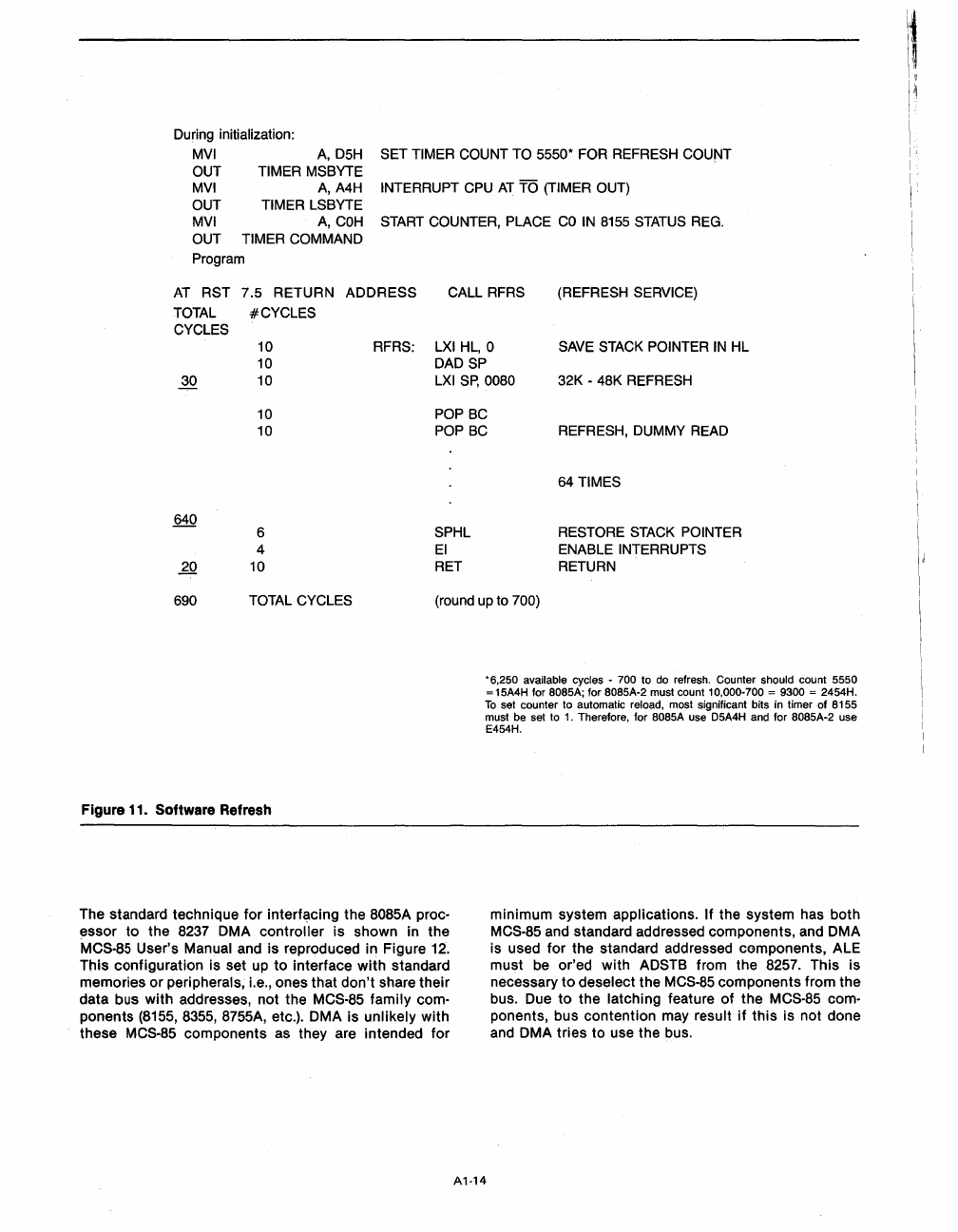
During initialization:
MVI
A,
D5H
SET TIMER COUNT TO 5550* FOR REFRESH COUNT
OUT TIMER
MSBYTE
MVI
A,
A4H
INTERRUPT CPU
AT
TO
(TIMER OUT)
OUT TIMER
LSBYTE
MVI
A,
COH
START
COUNTER, PLACE
CO
IN
8155
STATUS
REG.
OUT TIMER COMMAND
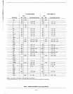
Program
AT
RST 7.5 RETURN ADDRESS CALL RFRS (REFRESH SERVICE)
TOTAL
#CYCLES
CYCLES
10
10
RFRS:
LXIHL,O
SAVE
STACK
POINTER
IN
HL
DADSP
30 10
LXI
Sp,
0080 32K - 48K REFRESH
10
10
POP
BC
POP
BC
REFRESH, DUMMY
READ
6
4
20 10
SPHL
EI
RET
64
TIMES
RESTORE
STACK
POINTER
ENABLE INTERRUPTS
RETURN
690 TOTAL CYCLES (round up to 700)
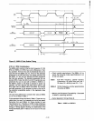
Figure 11. Software Refresh
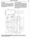
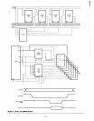
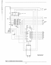
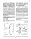
The standard technique
for
interfacing the 8085A proc-
essor
to
the 8237 DMA
controller
is
shown in
the
MCS·85 User's Manual and
is
reproduced in Figure 12.
This
configuration
is set up
to
interface
with
standard
memories
or
peripherals; i.e.,
one~
that
don't
share
their
data
bus
with
addresses,
not
the MCS-85
family
com·
ponents (8155, 8355, 8755A, etc.). DMA is
unlikely
with
these MCS·85
components
as they are intended
for
*6,250 available cycles - 700 to do refresh. Counter should count 5550
= 15A4H for 8085A; for 8085A-2 must count 10,000-700 = 9300 = 2454H.
To
set counter to automatic reload, most significant bits in timer of 8155
must be set to
1.
Therefore, for
808SA
use
D5A4H
and for 8085A-2 use
E454H.
A1·14
minimum
system
applications.
If
the system has
both
MCS·85 and standard addressed components, and DMA
is used
for
the standard addressed
components,
ALE
must
be or'ed
with
ADSTB from the 8257. This
is
necessary
to
deselect the MCS-85
components
from
the
bus. Due
to
the
latching feature
of
the
MCS·85 com·
ponents, bus
contention
may result
if
this
is
not
done
and
DMA
tries
to
use the bus.
11.
\'11
i
I'
1
I
I
I
I