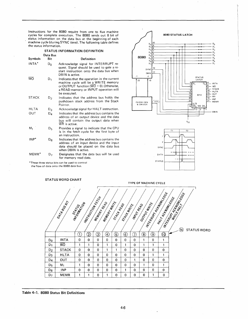
Instructions
for
the
8080
require
from
one
to
five
machine
cycles
for
complete
execution.
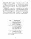
The
8080
sends
out
8
bit
of
status
information
on
the
data
bus
at
the
beginn
ing
of
each
machine
cycle
(during
SYNC
time).
The
following
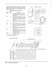
table
defines
the
status
information.
Symbols
INTA*
STATUS
INFORMATION
DEFINITION
Data
Bus
Bit
Definition
DO
Acknowledge
signal
for
I NTE R R UPT re-
quest.
Signal
should
be
used
to
gate
a re-
start
instruction
onto
the
data
bus
when
DBIN
is
active.
Dl
8080
STATUS
LATCH
/too
o 9
D,
D 8
27
D3 3
8080
D,
4
D5 5
~!
6
SYNC
~
DBIN
r22-
,
2
STATUS
22
15
LATCH
Indicates
that
the
operation
in
the
current
machine
cycle
will
be
a WR ITE
memory
or
OUTPUT
function
(WO = 0).
Otherwise,
a READ
memory
or
INPUT
operation
will
be
executed.
--4- D
5 '
~
Do
t--
~
STACK
HLTA
OUT
M,
INP*
MEMR*
D2
D3
D4
D5
De
D7
Indicates
that
the
address
bus
holds
the
pushdown
stack
address
from
the
Stack
Pointer.
Acknowledge
signal
for
HALT
instruction.
I
ndicates
that
the
address
bus
contains
the
address
of
an
output
device
and
the
data
bus
will
contain
the
output
data
when
WR
is
active.
Provides a signal
to
indicate
that
the
CPU
is
in
the
fetch
cycle
for
the
first
byte
of
an
instruction.
Indicates
that
the
address
bus
contains
the
address
of
an
input
device
and
the
input
data
should
be
placed
on
the
data
bus
when
DBIN
is
active.
Designates
that
the
data
bus
will
be
used
for
memory
read
data.
------g
16
18
8212
20
--~
22
CLOCK
GEN
I
lTTLI
&
DRIVER
~
g~;
MO
OS,
13 12
'(
1
~
SYNC
*These
three
status
bits
can
be
used
to
control
the
flow
of
data
onto
the
8080
data
bus.
ST
A TUS
f------f.J'-----1
STATUS
WORD
CHART
TYPE
OF
MACHINE
CYCLE
Do
INTA
000000010
WO
1 1 0 1 0 1 0 1 1
STACK
000
1
100
0 0
o
HLTA
o 0 0 0 0 0 0 0 1
OUT
o 0
000
0 1 0 0 o
1 0 0 0 0 0 0 1 0
De
INP o 0
000
1
000
o
MEMR
110100001
o
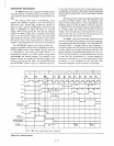
Table 4-1.
8080
Status Bit Definitions
4-6
Ta-
r,s-
'17""
~
:tt=
INTA
WD
STACK
HLTA
OUT
M1
INP
MEMR
DBIN


