


"data
output
delay"
interval
(tOO)
following
the
1>2
clock's
leading edge.
Data
on
the
bus
remains
stable
throughout
the
remainder
of
the
machine
cycle,
until
replaced
by
up-
dated
status
information
in
the
subsequent
T 1
state.
Observe
that
a
READY
signal
is
necessary
for
completion
of
an
OUTPUT
machine
cycle. Unless such an
indication
is
pres-
ent,
the
processor
enters
the
TW
state,
following
the
T2
state.
Data
on
the
output
lines
remains
stable
in
the
interim,
and
the
processing
cycle
will
not
proceed
until
the
READY
line again goes high.
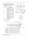
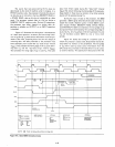
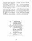
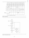
The
8080
CPU
generates
a WR
output
for
the
syn-
chronization
of
external
transfers,
during
those
machine
cycles
in
which
the
processor
outputs
data.
These
include
MEMORY
WR
ITE,
STACK
WR ITE,
and
OUTPUT.
The
negative-going leading edge
of
WR
is
referenced
to
the
rising
edge
of
the
first
1>1
clock
pulse
following
T2,
and
occurs
within
a brief
delay
(tOC)
of
that
event.
WR
remains
low
until
re-triggered
by
the
leading edge
of
1>1
during
the
state
following T
3.
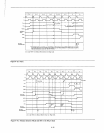
Note
that
any
T W
states
intervening
between
T 2
and
T 3
of
the
output
machine
cycle
will neces-
sarily
extend
WR,
in
much
the
same
way
that
DBIN
is
af-
fected
during
data
input
operations.
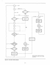
All
processor
machine
cycles
consist
of
at
least
three
states:
T"
T2,
and
T3
as
just
described.
If
the
processor
has
to
wait
for
a
response
from
the
peripheral
or
memory
with
which
it
is
communicating,
then
the
machine
cycle
may
also
contain
one
or
more
TW
states.
During
the
three
basic
states,
data
is
transferred
to
or
from
the
processor.
After
the
T3
state,
however,
it
becomes
difficult
to
generalize. T 4
and
T5
states
are
available, if
the
execution
of
a
particular
instruction
requires
them.
But
not
all
machine
cycles
make
use
of
these
states.
It
depends
upon
the
kind
of
instruction
being
executed,
and
on
the
particular
machine
cycle
within
the
instruction
cycle.
The
processor
will
termi-
nate
any
mach
ine cycle as
soon
as
its processing activities
are
completed,
rather
than
proceeding
through
the
T 4
and
T5
states
every
time.
Thus
the
8080
may
exit
a
machine
cycle
following
the
T3,
the
T 4,
or
the
T5
state
and
pro-
ceed
directly
to
the
T1
state
of
the
next
machine
cycle.
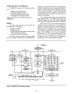
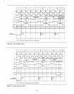
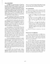
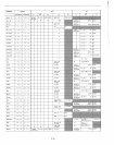
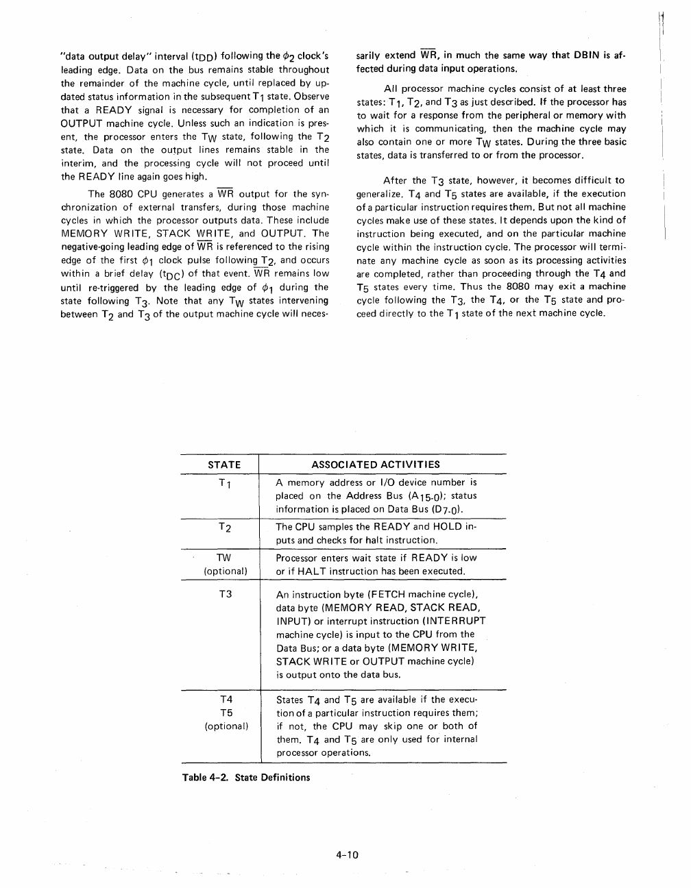
STATE
ASSOCIATED
ACTIVITIES
TW
(optional)
T3
T4
T5
(optional)
A
memory
address
or
I/O device
number
is
placed
on
the
Address
Bus (A15-0);
status
information
is
placed
on
Data
Bus (D7-0J.
The
CPU samples
the
READY
and
HOLD in-
puts
and
checks
for
halt
instruction.
Processor
enters
wait
state
if
READY
is
low
or
if
HALT
instruction
has
been
executed.
An
instruction
byte
(FETCH
machine
cycle),
data
byte
(MEMORY
READ,
STACK
READ,
INPUT)
or
interrupt
instruction
(INTERRUPT
machine
cycle)
is
input
to
the
CPU
from
the
Data
Bus;
or
a
data
byte
(MEMORY
WRITE,
STACK
WRITE
or
OUTPUT
machine
cycle)
is
output
onto
the
data
bus.
States
T 4
and
T5
are
available if
the
execu-
tion
of
a
particular
instruction
requires
them;
if
not,
the
CPU
may
skip
one
or
both
of
them.
T 4
and
T5
are
only
used
for
internal
processor
operations.
Table
4-2.
State
Definitions
4-10