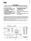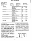
Sample Applications
Calculating
Oscilloscope
Blood
Analyzer
Programmable
Video Game
Process Control System
Line
Printer
APPLICATION
Intelligent Terminals
Gaming Machines
Cash Registers
Accounting and Billing Machines
Telephone Switching Control
Numerically Controlled Machines
Process Control
MCS-85™
APPLICATIONS
Intelligent
Terminal
N.C.
Machine
Digital
Multimeter
Graphic
Terminal
Automotive
Control
Navigation
Equipment
Vending
Machine
Spectrum
Analyzer
Front
End Processor
Credit
Verifier
PERIPHERAL DEVICES ENCOUNTERED
Cathode Ray
Tube
Display
Printing Units
Synchronous and Asynchronous data lines
Cassette
Tape
Unit
Keyboards
Keyboards, push buttons and switches
Various display devices
Coin acceptors
Coin dispensers
Keyboard or Input Switch Array
Change Dispenser
Digital Display
licket
Printer
Magnetic Card reader
Communication interface
Keyboard
Printer Unit
Cassette or other magnetic tape unit
"Floppy" disks
Telephone Line Scanner
Analog Switching Network
Dial Registers
Class of Service Parcel
Magnetic or Paper
Tape
Reader
Stepper Motors
Optical Shaft Encoders
Analog-to-Digital Converters
Digital-to-Analog Converters
Control Switches
Displays
Disk
Controller
Patient
Monitor
Network
Analyzer
Frequency Synthesizer
MCS-85™
COMPONENTS
8275
8085A
8155
8355
8251
8279
8279 8085A
8355
8155
8279
8085A
8155
8355
8273
8279
8085A
8155
8355
8257
8271
8253
8085A
8355
8155
8155
8085A
8355
8155
8085A
8355
8279
Baud Rate Generator
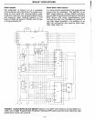
Shown in Figure 2 is a minimum system con-
figuration
with the 8156
timer
output
connected
to
an 8085 interrupt input.
the required baud rate. As shown in Figure
1,
the minimum system supports serial com-
munications
with only the addition
of
the
send
and receive interface circuits.
This configuration
allows convenient use
of
the
timer
as a baud rate generator. A 6.144 MHz
crystal is used as the frequency control
ele-
ment
of
the 8085A, providing integral divisors
for
the standard baud rates
(300,
600, 1200,
2400,4800,9600
baud). The
timer
is programmed
with
the
appropriate divisor (Figure
1)
for the
selected baud rate resulting in one pulse on the
timer
output for each
bit
cell time. The
clock
output
(elK)
of
the 8085A is used
to
clock
the
timer
(TIMERIN). The frequency
of
this
clock
is
one-half the crystal frequency
or
in
this
exam-
ple 3.072 MHz. TIMEROUT now provides a
crystal controlled pulse train at the baud rate
selected.
Serial Communications
By feeding the TIMEROUT signal
of
the
8156
back
to
the
edge triggered
RST
7.5
input
of
the
8085A,
the
processor can be interrupt driven at
A1-2
The SID (SERIAL INPUT DATA) line and
the
SOD
(SERIAL
OUTPUT DATA) line are connected
directly
to
a TTY or
RS232
interface
circuit.
Assuming inverted
data
at the SID input, a
direct connection is made
to
the RST6.5
input
for detection
of
the
start
bit.
Additional insight into using the 8085's serial
I/O
lines in communications application can be found
in Section 2 of this Appendix.
BAUD
RATE
COUNT (DECIMAL)
300
10,240
600
5,120
1200
2,560
2400
1,280
4800
640
9600
320
FIGURE
1.
BAUD
RATES


