


FUNCTIONAL DESCRIPTION
SIGNALS
THALT
THALl
THAll
THOLD THOLD
Tl
CLK
~
~
~
~
~
~
ALE
J
L-
LOW
PRIORI".
-=-'
HOLD
I
\
IJ
INTERRUPT CYCLE
EXITS
HALT
IMMEDIATELY AFTER
HLDA
I
-r""'
HOLD
REMOVED
INTERRUPT ACCEPTED
HERE CAUSES SAMPLING TO BE INHIBITED -
LOW PRIORITY
--
INHIBITING HIGHER INTERRUPTS (EVEN TRAP)
INTERRUPT(S)
I \
V
HIGH PRIORITY
'I
INTERRUPT(S)
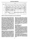
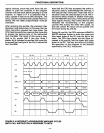
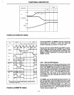
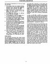
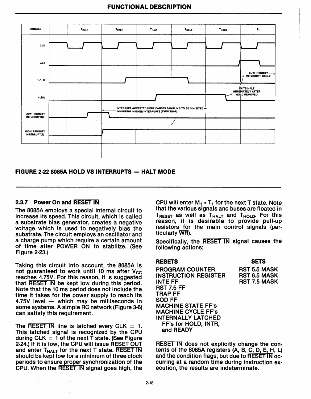
FIGURE 2-22
SOSSA
HOLD VS INTERRUPTS -
HALT
MODE
2_3.7
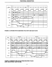
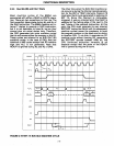
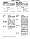
Power On and RESET IN
The
SOS5A
employs a special internal circuit
to
increase
its
speed. This circuit, which is called
a substrate bias generator, creates a negative
voltage which is used to negatively bias the
substrate.
The
circuit employs
an
oscillator and
a charge pump which require a certain amount
of
time after
POWER
ON
to stabilize.
(See
Figure
2-23.)
Taking this circuit into account, the
SOS5A
is
not guaranteed to work until
10 ms after Vcc
reaches
4.75V.
For this reason,
it
is suggested
that
RESET
IN
be
kept low during this period.
Note that the
10 ms period does not include the
time
it
takes for the power supply to reach
its
4.75V
level - which may
be
milliseconds in
some systems. A
simple
RC
network (Figure
3-6)
can satisfy this requirement.
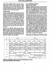
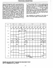
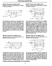
The
RESET
IN line is latched every
ClK
= 1.
This latched signal is recognized by the
CPU
during
ClK
= 1
of
the next T state.
(See
Figure
2-24.)
If
it
is low, the
CPU
will issue
RESET
OUT
and enter T HALT for the next T state.
RESET
IN
should
be
kept low for a minimum of three clock
periods
to
ensure proper synchronization
of
the
CPU.
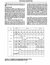
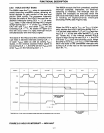
When the
RESET
IN
signal goes high, the
2-18
CPU
will enter
M1
•
T1
for the next T state. Note
that the various
signals and buses are floated in
T
RESET as well as T HALT and T HOLD. For this
reason,
it
is desirable
to
provide pull-up
resistors for the main control signals (par-
ticularly
WR).
Specifically, the
RESET
IN
signal causes the
following actions:
RESETS
PROGRAM
COUNTER
INSTRUCTION
REGISTER
INTE FF
RST
7.5
FF
TRAP
FF
SOD
FF
MACHINE
STATE
FF's
MACHINE
CYCLE
FF's
INTERNAllY
lATCHED
FF's for
HOLD, INTR,
and
READY
SETS
RST
5.5
MASK
RST
6~5
MASK
RST
7.5
MASK
RESET
IN
does not explicitly change the con-
tents of the
SOS5A
registers
(A,
B,
.C,
0,
E,
H,
l)
and the condition flags, but due
to
RESET
IN
oc-
curring at a random time during instruction
ex-
ecution, the results are indeterminate.