


FUNCTIONAL DESCRIPTION
• The 8085A, before
respondin~
to
the
RST
7.5
interrupt, receives a
RES
T
IN
signal
from
an
external source;
this
also ac-
tivates the internal reset.
• The 8085A executes a SIM instruction,
with
accumulator bit 4 previously set
to
1.
(See
Figure
2-4.)
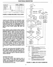
The third type
of
hardware interrupt is
TRAP.
This input is not subject
to
any mask or inter-
rupt
enable/disable instruction. The receipt
of
a
positive-going edge on the TRAP input triggers
the processor's hardware interrupt sequence,
but the
pulse must be held high until
acknowledged internally
(see Figure 2-68).
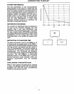
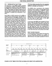
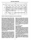
The
sampling
of
all interrupts occurs on the
descending edge
of
CLK, one cycle before the
end
of
the instruction in which the interrupt in-
put is activated.
To
be recognized, a valid inter-
rupt must occur at
least 160 ns before sampling
time
in the8085A, or
150
ns in the 8085A-2. This
means that
to
guarantee being recognized,
RST
5.5 and 6.5 and TRAP need
to
be held on for at
least
17
clock states plus
160
ns
(150
for
8085A-2), assuming that the interrupt might ar-
rive
just
barely too late to.be acknowledged dur-
ing a particular instruction, and that the follow-
ing instruction might
be
an 18-state CALL. This
timing assumes no
WAIT or HOLD cycles are
used.
The way interrupt masks are set and read is
described in Chapter 4 under the
RIM
(read in-
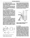
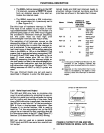
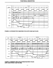
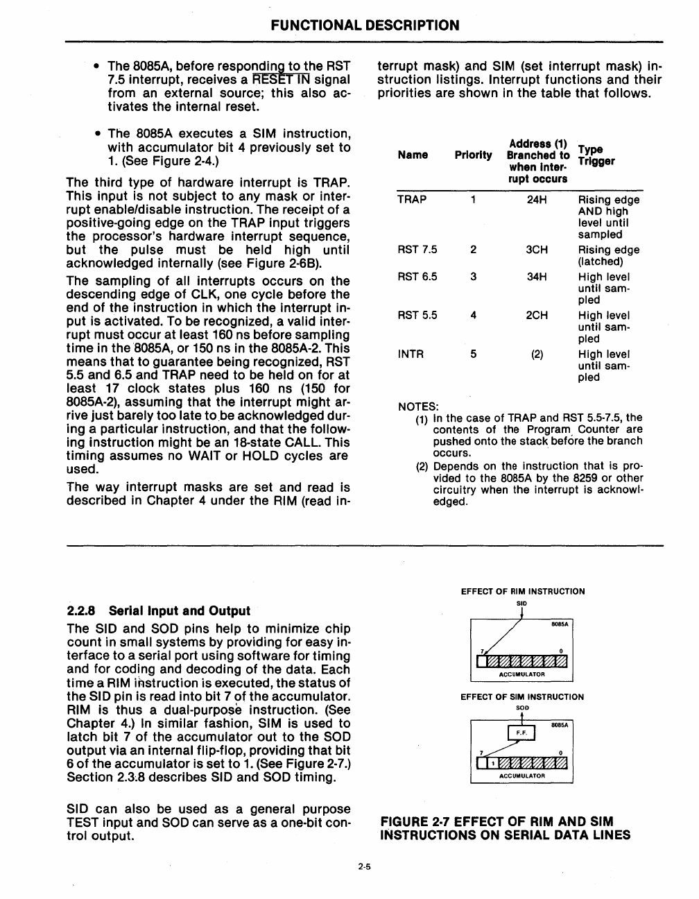
2.2.8 Serial
Input and Output
The
SID and
SOD
pins help
to
minimize chip
count in
small systems by providing for easy in-
terface
to
a serial port using software for timing
and for coding and decoding
of
the data. Each
time
a
RIM
instruction is executed, the status of
the
SID pin is read into bit 7
of
the accumulator.
RIM
is thus a
dual-purpo~e
instruction.
(See
Chapter
4.)
In
similar fashion, SIM is used to
latch bit 7
of
the accumulator
out
to
the
SOD
output via an internal flip-flop, providing that bit
6
of
the accumulator is set
to
1.
(See
Figure
2-7.)
Section
2.3~8
describes SID and SOD timing.
SID can also be used as a general purpose
TEST input and
SOD
can serve as a one-bit con-
trol
output.
2-5
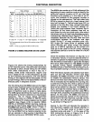
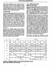
terrupt mask) and
SIM
(set interrupt mask) in-
struction
listings. Interrupt functions and their
priorities are shown
in
the table that follows.
Address
(1)
Type
Name Priority
Branched
to
when Inter·
Trigger
rupt occurs
TRAP
24H
Rising edge
AND high
level until
sampled
RST
7.5
2
3CH
Rising edge
(latched)
RST
6.5
3
34H
High level
until sam-
pled
RST
5.5
4
2CH
High level
until
sam-
pled
INTR 5
(2)
High level
until
sam-
pled
NOTES:
(1)
In
the case
of
TRAP and
RST
5.5-7.5,
the
contents
of
the Program Counter are
pushed onto the stack. before the branch
occurs.
(2)
Depends on the instruction that is pro-
vided
to
the
80S5A
by the 8259
or
other
circuitry when the interrupt is acknowl-
edged.
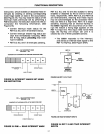
EFFECT OF RIM INSTRUCTION
SID
+
B08SA
I
ACCUMULATOR
EFFECT OF SIM INSTRUCTION
SOD
B08SA
F.F.
ACCUMULATOR
FIGURE
2-7
EFFECT OF
RIM
AND SIM
INSTRUCTIONS
ON
SERIAL DATA LINES