THE INSTRUCTION SET
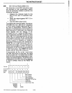
SIM (Set Interrupt Masks)
(8085
only)
The execution
of
the SIM instruction uses
the contents
of
the
accumulator (which
must be
previously loaded)
to
perform the
following functions:
• Program the interrupt mask for the
RST
5.5, 6.5, and
7.5
hardware inter-
rupts.
• Reset
the
edge-triggered
RST
7.5
in-
put latch.
•
Load the SOD
output
latch.
To program
the
interrupt masks,
first
set ac-
cumulator
bit
3
to
1 and set
to
1 any
bits
0,
1,
and
2,
which disable interrupts
RST
5.5,
6.5, and
7.5,
respectively. Then do a SIM in-
struction.
If
accumulator
bit 3 is 0 when the
SIM
instruction
is executed, the interrupt
mask register
will not change. If ac-
cumulator
bit
4 is 1 when the SIM instruc-
tion is executed, the
RST
7.5
latch is then
reset.
RST
7.5
is distinguished by the fact
that
its
latch is always set by a rising edge
on the
RST
7.5
input pin, even
if
the jump
to
service routine is inhibited by masking.
This
latch remains high until cleared by a
RESET IN, by a SIM Instruction with ac-
cumulator
bit
4 high, or by
an
internal pro-
cessor acknowledge
to
an
RST
7.5
interrupt
subsequent
to
the removal
of
the mask (by
a
SIM instruction). The
RESET
IN
signal
always
sets all three
RST
mask bits.
If
accumulator
bit 6 is at
the
1 level when
the
SIM
instruction
is
executed, the
state
of
accumulator bit 7 is loaded
into
the
SOD
latch
and
thus
becomes available for inter-
face
to
an
external device. The SOD latch
is
unaffected by the SIM instruction
if
bit
6
is
O.
SOD is always reset by the RESET IN
signal.
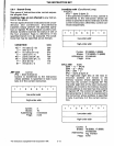
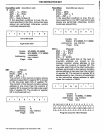
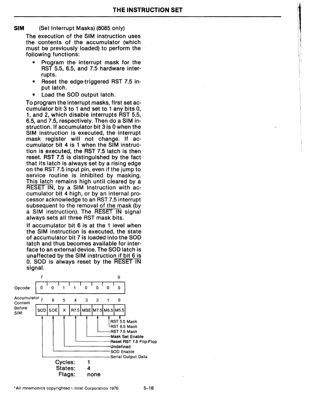
7
0
Opcode:
I
0
0
0
o.
0
0
Accumulator
7
Content
6
5
4
3 2 0
Before
SIM:
RST
5.5
Mask
RST
6.5 Mask
RST
7.5
Mask
'-----Mask
Set Enable
~----Reset
RST 7.5 Fllp·Flop
'--------Undefined
'---------SOD
Enable
'-----------Serial
Output Data
Cycles: 1
States: 4
Flags: none
• All mnemonics copyrighted
(c-,
Intel Corporation 1976.
5-18


