


SOD are ideal for many applications which involve
critical
I/O timing, the timing techniques used here
may be
of
interest
to
software designers. Accord-
ingly, the mathematical derivation
of
the timing
parameters
is
included in this analysis,
as
well
as
a
justification for the BRID algorithm. The algebra
involved might be a bit
too
tedious for designers
unconcerned with generating software delays.
If
so,
they (and other bored readers) have the freedom
of
choice to skip over the sections they find objec-
tionable.
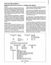
OUTPUT ROUTINE
It would seem natural
to
write data in the standard
format
in
three stages:
output
a zero start bit, then
the 8 data bits (using a loop sequence), then the
stop bits. Each stage would incorporate its own
appropriate delay and
output
sections, leading
to
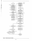
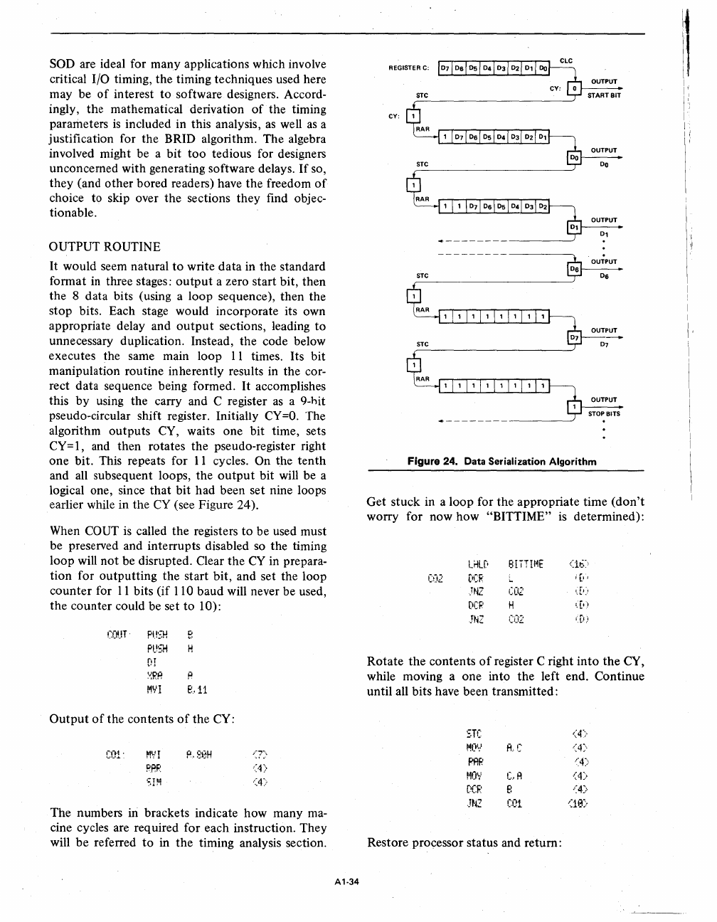
unnecessary duplication. Instead, the code below
executes the same main loop
11
times. Its bit
manipulation routine inherently results in the cor-
rect data sequence being formed.
It
accomplishes
this
by
using the carry and C register
as
a 9-hit
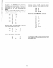
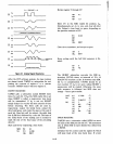
pseudo-circular shift register. Initially
CY=O.
The
algorithm outputs CY, waits one bit time, sets
CY=I, and then rotates the pseudo-register right
one bit. This repeats for
11
cycles. On the
tenth
and all subsequent loops, the
output
bit will be a
logical one, since
that
bit had been set nine loops
earlier while in the
CY
(see Figure 24).
When
COUT
is
called the registers
to
be used must
be preserved and interrupts disabled so the timing
loop will
not
be disrupted. Clear the
CY
in prepara-
tion for outputting the start bit, and set the loop
counter
for
11
bits (if 110 baud will never be used,
the counter could be set
to
10):
COUTo
PUSH
e
PUSH
H
fi1
:v:RP.
R
t~VI
e.11
Output
of
the contents
of
the CY:
COl'
MVI
PAR
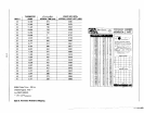
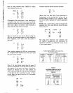
The numbers in brackets indicate how many ma-
cine cycles are req uired for each instruction. They
will
be
referred
to
in the timing analysis section.
A1-34
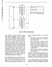
REGISTER C:
STC
CV:
OUTPUT
START
BIT
OUTPUT
DO
OUTPUT
01
OUTPUT
06
OUTPUT
STOP BITS
-----------------~
Figure 24. Data Serialization Algorithm
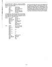
Get stuck in a loop for the appropriate time
(don't
worry for now how "BITTIME"
is
determined):
LHlC'
8IiTIl~E
(1t.::
CO2
[:t(:R
.
[I
.TNZ
CO2
•.
:[1
!
(lCP
H
'.
[.:.
JN2
CO2
I,D.!
Rotate the contents
of
register C right
into
the CY,
while moving a one into the left end. Continue
until all bits have been transmitted:
STC
MOV
A.·C
PAP
t'10~'
C.R
(:OCF.:
B
.J~t2
COl
Restore processor status and return:
!
I
I,
I'"~
I
I
II
I
I
I
,
I'