


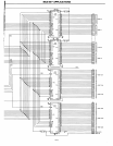
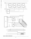
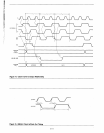
Data
The data path to the
2117s
is through two sets of buffers
to
account for memory being off board.
To
determine
bus
timing
it
is
helpful
to
know that Write data
is
not guaranteed to be
valid from the
BOB5A
until 40
ns
after the leading edge of the
write
control signal.
On
account of this and
the
delay times for
the buffers
it
i~ecessary
to delay the cycle request
on
a
write until the
WR
signal goes
low.
The solution shown still
does not require wait states.
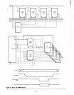
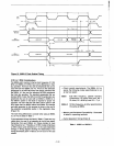
An
inhibit memory signal
is
also
involved. This
is
useful when using memory address space
overlap such as the case with bootstrap
ROM
(which would
be necessary
in
this system if a full 64K of dynamic
RAM
is
used).
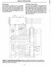
Refresh
Dynamic RAMs are
generally refreshed
in
two different
modes; burst
(Le.,
all
at
once every 2
ms)
and distributed
(one row every
(2
ms/number of rows) period of time). The
schematic shown provides for a distributed refresh where
refresh requests are
applied
to
the Hold request input of the
BOB5A
(not shown). This signal needs
to
occur
at
least once
every
15
jJsec
((2ms/12B rows
to
be
refreshed) - HOLD
to
HLDA delay) and can
be
generated through a baud rate
timing chain,
Intel 3222, one shots or other similar devices.
Another approach to refresh
could qualify the refresh cycles
with program fetch cycles (use status lines). If program mem-
ory
is
in
static
RAM
or
ROM
and the dynamic
RAM
bus can
be
isolated, refresh cycles can
be
performed with
no
over-
head.
Instead of using the HOLD feature of
the
BOB5A,
refresh
can
be
hidden
in
the program fetch
and
decode. Further
considerations for refresh
include proper handling of resets
and excessive
hold times from other peripherals
to
be
certain
the memory is being refreshed adequately.
Some applications don't require high
CPU
efficiency and
re-
quire a very inexpensive method to refresh their dynamic
RAM.
Since writing, reading or performing special refresh
cycles all refresh a particular
row,
why not do "dummy" reads
to refresh?
To
use this technique memory must
be
mapped
on
a one
to
one correspondence with the address space.
This
will allow the programmer
to
read one byte
in
each
physical row
in
the
2117s,
thereby refreshing that
row.
A
simple software routine can
be
devised
to
refresh
16K
bytes
of
RAM.
If more dynamic
RAM
than this
is
desired
it
can
be
accomplished
by
specially enabling all
the
desired
RAS
sig-
nals
via
an
BOB5A
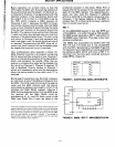
output port. First let's analyze how many
CPU cycles are available
in
the 2ms period:
2ms/(320 ns/cycle)
= 6,250 cycles
for
BOB5A@
3.125 MHz
2ms/(200 ns/cycle)
= 10,000 cycles
for
BOB5A-2@
5.0 MHz
A1-13
If there
is
a convenient component that can count
BOB5A
cycles
(BOB5A
CLKOUT) and interrupt the
BOB5A,
you're
home free.
An
example of such a device
is
the
B155
in
the
MCS-B5 family.
On
the
B155
one can use the
TO
(timer out)
pin
to
interrupt the
CPU
everytime a refresh needs
to
be
performed and
an
interrupt service routine could dummy read
12B
consecutive locations and return to CPU operation.
(12B
reads are necessary
to
completely refresh the full
16K
bytes
of
2117
memory.) The highest priority interrupt should be
used
for
this
to
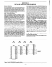
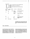
insure that refresh occurs. Figure
11
is an
example program
to
perform this burst dummy read refresh.
This routine
basically uses
64
pops
of the stack, each reading
two consecutive locations
in
the memory. Note that this rou-
tine destroys the contents of registers
B,
C and D
in
the
BOB5A.
The user
may
want
to
save these registers
in
the
routine before performing the software refresh.
If memory
space
is
more valuable than
CPU
efficiency, the POPs can
be performed
in
a loop instead of a string, saving additional
memory.
This routine requires
690 cycles which
is
about
11
% of the
available
BOB5A
CPU
cycles, or
7%
of the available
BOB5A-
2 cycles. If this
is
acceptable and there
is
a counter available,
you
can't find a cheaper
way
to
do refresh. Note that as
processor speeds become
faster,
this overhead becomes
proportionately
less and more attractive as
an
alternative.
Again,
as
with any refresh routine, reset and excessive holds
must be dealt with
to
guarantee proper refresh.
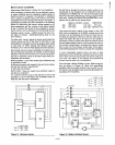
DMA (Direct Memory Access)
DMA
is
becoming more common
in
the microcomputer sys-
tem for many applications. Some examples include
the
B271
floppy disk controller and refreshing a CRT via an
B275
CRT
Controller.
It
is always helpful
to
reduce the overhead of the
DMA
(as
DMA can tie
up
the system bus) whenever possible.
In
many applications, where program memory is resident in
ROM
or
PROM,
DMA
cycles
can
be
performed
in
coincidence
with
op
code fetch. This will make them invisible
to
the
CPU
as described for Refresh
in
the Refresh section of the 2117
dynamic
RAM
example.
In
the dynamic
Ram
system, Refresh requests can be
made on the DMA
controller
via
the
DRO lines,
with
the
B237
in a rotating
priority
mode
to
insure refreshing
is
done.
Another
technique
would
be
to
devise an arbiter
for
DMA and refresh requests at
the
processor
hold in-
put.
With
this
technique the designer
must
not
allow
DMA
to
monopolize the bus when refresh
is
needed.