Software
The
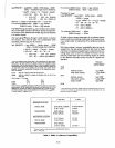
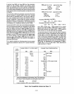
software (at end of section) for this application illustrates
several features of
·the 8085A, such as the programming of
the
SOD line, interrupts and 8155 counter. Additionally, an
example of a block search routine is illustrated.
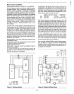
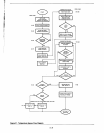
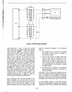
Figure
21
is a flow diagram of the program. It has been cross
referenced with program lines to the actual software for the
reader's convenience. Following through the flow diagram it
is seen that the interrupts are disabled in the beginning as the
one shot is outputting a high
level on its a output and interrupt
pin 6.5
is
high level sensitive. However, this high level will not
be recognized until the
level goes low and then high again. If
the
user
would
prefer
a
positive
pulse
interrupt
the
8085A a
dual one shot can be used with one triggering the other,
or
just a simple inverter. Starting and loading the counter is as
described in the 8155 data sheet with the Port addresses
being given in the previous Table (7). Code
lines 18-23 repre-
sent placing the counter in the counter mode (single terminal
count pulse at the end of count) and starting the count, having
the
count
clocked
by
the
8085A
clock
out
pin. Reading
the
counter is not as straight forward and will be approached
shortly.
Code lines 28-32 are representative of programming
the
SOD line to output a pulse. This pin is intended for serial
I/O
interfaces such as a teletype, but as seen in this applica-
tion, it can also be used as a single
I/O
port.
After the pulse is presented to the one shot, the interrupts
enabled, the processor idles (lines 36, 37; Halt could have
just as easily been used) until interrupted. Through the design
of this
application it was known that the down counter would
never reach terminal count, as it is only being used as a pulse
to
digital count converter.
To
read in
the
count value it is best that the counter is first
stopped. The
least and most significant bytes of the count
length register in the 8155 are read using the same port
addresses
as
was used during loading the counter, as seen
in code
lines 42-47. If one looks at this value and knows how
many
pulses occurred, he would come to the conclusion that
there is a gross discrepancy! The reason for this is that the
counter
in
the 8155/6
was
designed to make its square wave
function generation easy and when used in the counter mode,
it counts by two's. For this
application (where length of time is
mapped into a temperature) and other
similar event timing
applications it is imperative to have an
intelligible count re-
turned from the 8155.
The
counter in the 8155 is essentially a count down by 2
counter. After
it
counts down by 2 the initial value loaded by
the user, it
reloads the initial count (initial count
-1
if odd) and
counts down by 2 again
until terminal count is reached. When
reading the counter, the
least significant bit of the counter
does not represent the
least significant bit of the count, but
which
half of the countdown operation you are in. If this bit
equals
1,
the 8155/6 counter is counting down by 2 in the first
half, and if it is zero you are in the second half of the opera-
tion. Because of this method of down counting there are two
restrictions
placed on its use:
A1-28
1.
The user can not use the initial value of 1 to detect only
one pulse.
2.
The user can not discern (through reading the counter)
whether
exactly one or two pulses on the timer input pin
has occurred if he
loaded in an initial odd count (does not
apply to even). After three pulses the user can determine
exactly how many pulses occurred. Note that this restric-
tion
only applies to reading the counter, the
TO
pin pulses
correctly after the correct number of
pulses regardless of
what is read from the counter.
The first
pulse to the 8155/6 counter (high level sensitive)
loads the count length register, which says that the counter is
not
readable until a pulse occurs. If the user tries to read
before a
pulse is provided he will read a previous
or
old
value.
Now what is done with the value read?
Good question. An adjustment routine to convert this
value
read to an actual count can be summarized as follows:
1.
Read in
16
bit count length register.
2.
Reset the upper two bits (mode bits).
3. Reset carry and rotate right
all 16 bits through carry.
4.
If carry is set add 1/2 of full original count (1/2 (full count
-1)
if full count is odd).
In
the software for this application is a general purpose rou-
tine to do this; lines 179-199.
To
call this routine it is assumed
that the lower order byte of the counter is in register
C,
higher
order byte in register B and
full original count is,in HL. Con-
tents of
H,
L,
Band
C are destroyed returning actual count
in
BC register pair.
To
obtain the number of pulses that
occurred, subtract this number from
full original count and
add
1.
Converting this remaining count to an actual temperature can
be done by various methods but it was chosen to do a soft-
ware map through the use of a
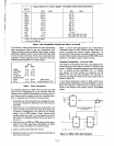
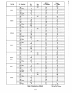
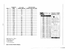
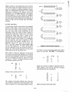
block search routine. Table 8
presents approximations of what the remaining count should
be for each temperature.
To
keep the software simple it was
only necessary to compare the most significant byte to a list
to find the appropriate temperature. This search routine is set
up to find a
"less than" match, incrementing the HL register
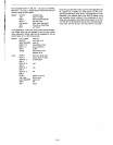
as a pointer when a compare is made. The code for this
search routine is in lines 118-144 and is optimized to be a fast
8 byte
block search. This search routine can be made to
search for a match by replacing
all return on carry with return
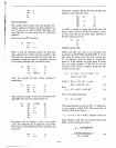
on zero. The performance of this subroutine is as follows:
Byte time
=
(11
+ (166/8) N)
CC/N
= (11/N + 20.8) CC
where: CC = microseconds per clock cycle
N
= total number of bytes searched
Byte time
= time per byte searched
I.~
I
~
I,
i
I
I'I
Iii
!
I'
I
I
I
I
I


