FUNCTIONAL DESCRIPTION
~f
WR.
The
ADo-AD7
lines are guaranteed
to
be
stable both before and after the rising edge
of
WR.
1/0
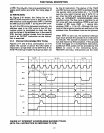
WRITE (lOW):
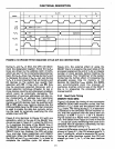
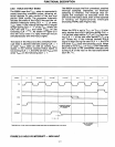
As Figure
2-16
shows, the timing for an
1/0
WRITE (lOW) machine cycle is the same as an
MW machine
cycle except that
101M
= 0 during
the MW
cycle and
101M
= during the lOW cycle.
As with the lOR cycle discussed previously, the
address used in
an
lOW cycle is the
1/0
port
number which is
duplicated on both the high
and
low bytes
of
the address bus. In the case
of
lOW, the port number comes from the second
byte
of
an
OUTPUT
instruction as the instruc-
tion is executed.
2.3.4
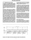
Interrupt Acknowledge (INA) Timing
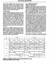
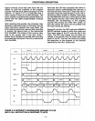
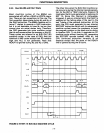
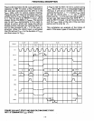
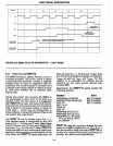
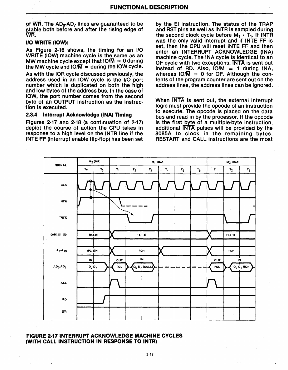
Figures
2-17
and
2-18
(a
continuation
of
2-17)
depict the course of action the
CPU
takes in
response
to
a high level
on
the INTR line
if
the
INTE FF (interrupt enable flip-flop) has been set
M2(MR)
SIGNAL
T2
T3
T1
T2
by the
EI
instruction.
The
status
of
the TRAP
and
RST
pins as well
as
INTR is sampled during
the second
clock cycle before
M1
• T
1
.
If
INTR
was the only valid interrupt and
if
INTE FF is
set, then the
CPU
will reset INTE FF and then
enter
an
INTERRUPT ACKNOWLEDGE (INA)
machine
cycle. The INA cycle is identical
to
an
OF cycle with two exceptions. INTA is sent out
instead
of
RD.
Also,
101M
= 1 during INA,
whereas
101M
= 0 for OF. Although the con-
tents of the program counter are sent out on the
address
lines, the address lines can be ignored.
When
INTA is sent out, the external interrupt
logic must provide the opcode
of
an instruction
to
execute. The opcode is placed
on
the data
bus and read in by the processor.
If
the opcode
is the first byte
of
a multiple-byte instruction,
additional
INTA pulses will be provided by the
8085A
to
clock
in
the
remaining
bytes.
RESTART
and CALL instructions are the most
M1
(INA)
M2
(INA)
T3
- T4
TS
TS
Tl
T2
T3
ClK
u:
~lr
Lr
U-
U-
U-
U-
U-
V
Lr
U-
~
INTR
V
~
--- -
~
INTA
I
IO/M,S1,SO
(0,1,0)
~
(1,1,1)
AS-A1S
(PC·llH
~
PCH
X
IN
OUT
~
AOO·A07
0
0
.0
7
}
IE:
)-
00.[)7
(CAll}-
---
---
ALE
n
RD
I
WR
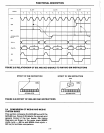
FIGURE 2-17 INTERRUPT ACKNOWLEDGE MACHINE CYCLES
(WITH CALL INSTRUCTION IN RESPONSE TO INTR)
2·13
-
\
r
X
(1,1,1)
X
PCH
€
IN
---
)-
0
0
-0
7
(82) }
n


