inter
WAVEFORMS (Continued)
WAIT
HOLD
I-
___
t
nr
............
HlDA
INT
INTE
8080Al8080A·1/8080A·2
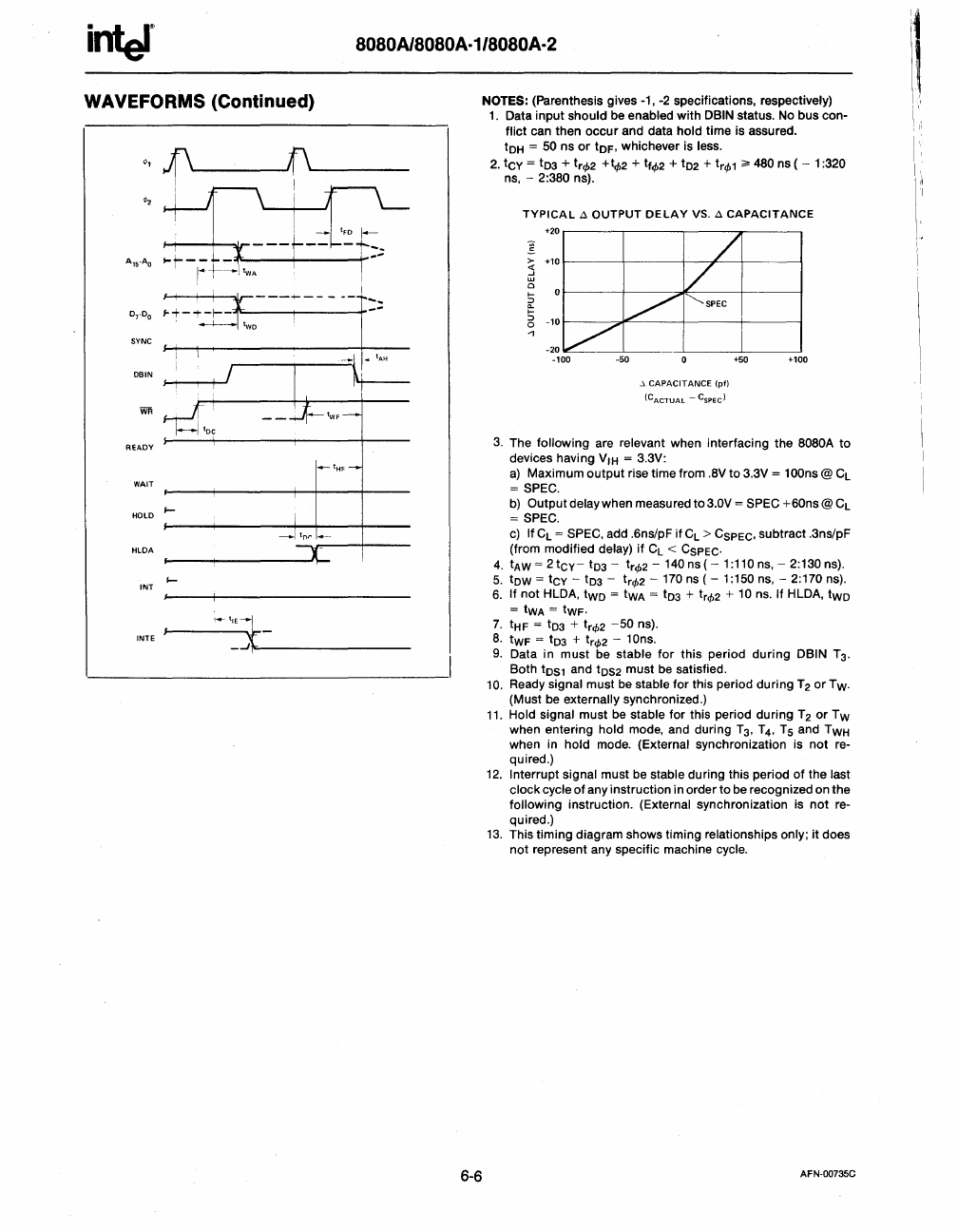
6-6
NOTES: (Parenthesis gives -1,
-2
specifications, respectively)
1.
Data input should be enabled with DBIN status.
No
bus con-
flict can then
occur
and data hold time is assured.
tOH
= 50 ns
or
tOF,
whichever is less.
2.
tCY
= t03 +
tr<f>2
+t,p2 +
tf<f>2
+ t02 +
tr<f>1
;;.
4BO
ns ( - 1 :320
ns,
-
2:3BO
ns).
TYPICAL A OUTPUT DELAY
VS.
A CAPACITANCE
>-
~
o
I-
12
I-
:::l
o
..,
..\
CAPACITANCE
(pI)
(CACTUAL - C
SPEC
)
+100
3.
The following are relevant when interfacing the
BOBOA
to
devices having
V,H
= 3.3V:
a)
Maximum
output
rise time from
.BV
to 3.3V = 100ns @
CL
=
SPEC.
b)
Output delay when measured to3.0V = SPEC
+60ns@CL
=
SPEC.
c)
If
CL
= SPEC, add .6ns/pF if
CL
>
CSPEC,
subtract .3ns/pF
(from modified
delay)
if
CL
<
CSPEC.
4.
tAW
= 2
tCY-
t03 - t
r
<f>2
-
140
ns ( - 1 :110
ns,
- 2:130 ns).
5.
tow
=
tCY
- t03 -
tr<f>2
-
170
ns ( - 1 :150
ns,
- 2:170 ns).
6.
If
not
HLDA,
two
=
tWA
=
tD3
+
tr<f>2
+
10
ns.
If HLDA,
two
=
tWA
=
tWF·
7.
tHF
= t03 +
tr<f>2
-50
ns).
B.
tWF
= t03 +
tr<f>2
- 10ns.
9.
Data in must be stable
for
this period during DBIN
T3.
Both
tOS1
and
tOS2
must
be
satisfied.
10.
Ready signal must
be
stable
for
this period during
T2
or Tw.
(Must be
externally synchronized.)
11.
Hold signal must be stable for this period during T 2
or
Tw
when entering hold mode, and during
T3, T4,
Ts
and
TWH
when in hold mode. (External synchronization is not re-
quired.)
12.
Interrupt signal must be stable during this period of the last
clock
cycle of any instruction in order to be recognized on the
following instruction. (External synchronization is
not
re-
quired.)
13.
This timing diagram shows timing relationships only; it does
not represent any specific machine
cycle.
AFN·00735C
!1
I',
