


intJ
8085AH/8085AH-2/8085AH-1
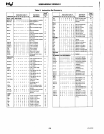
Table
1.
Pin Description (Continued)
,-------,-----,----------------------,
Symbol
TRAP
Type
Name
and Function
I
Trap:
Trap
interrupt
is a
non-
maskable RESTART interrupt. It is
recognized
at
the
same
time
as
INTR
or
RST
5.5-7.5. It is unaffected
by any mask
or
Interrupt Enable. It
has
the
highest
priority
of
any inter-
rupt.
(See Table 2.)
Reset
In:
Sets
the
Program
Counter
to
zero and resets the Inter-
rupt
Enable and
HlDA
flip-flops.
The data and address buses and
the
control
lines are 3-stated
during
RESET and because of
the
asyn-
chronous
nature of
RESET,
the pro-
cessor's internal registers and
flags
may be altered by RESET with un-
predictable results.
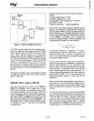
RESET
IN
is a
Schmitt-triggered
input,
allowing
connection to
an
R-C
network
for
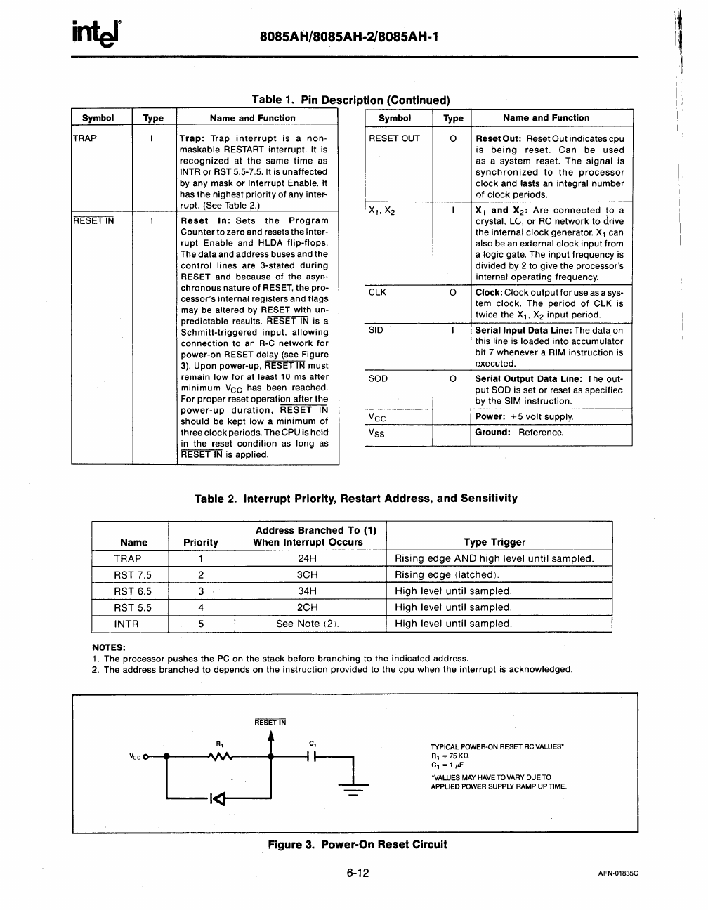
power-on RESET delay (see Figure
3).
Upon power-up, RESET
IN
must
remain
low
for
at least
10
ms after
minimum
Vee
has been reached.
For
proper
reset operation after
the
power-up
duration,
RESET
IN
should
be kept
Iowa
minimum
of
three
clock
periods. The CPU is held
in
the
reset
condition
as long
as
RESET
IN
is applied.
Symbol
RESET OUT
X
1
,X2
ClK
SID
SOD
Vee
Vss
Type
a
I
a
I
a
Name
and
Function
Reset
Out:
Reset
Out
indicates cpu
is
being
reset.
Can
be
used
as a
system
reset. The
signal
is
synchronized
to
the
processor
clock
and lasts an integral
number
of
clock periods.
X
1
and
X2:
Are
connected
to
a
crystal,
le,
or
RC
network
to
drive
the internal
clock
generator. X
1
can
also be an external clock
input
from
a
logic gate. The input frequency is
divided by 2
to
give the processor's
internal operating frequency.
Clock:
Clock
output
for
use
as
a sys-
tem
clock. The
period
of
ClK
is
twice the X
1
,
X
2
input period.
Serial
Input
Data Line: The data on
this
line is loaded
into
accumulator
bit
7 whenever a RIM instruction is
executed.
Serial
Output
Data Line: The out-
put
SOD is set or reset
as
specified
by
the SIM instruction.
Power:
+5
volt
supply.
Ground:
Reference.
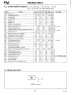
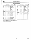
Table
2.
Interrupt
Priority, Restart Address, and
Sensitivity
Address
Branched
To
(1)
Name
Priority
When
Interrupt
Occurs
Type
Trigger
TRAP
1
24H Rising edge
AND
high
level
until
sampled.
RST 7.5
2
3CH
Rising edge (latched).
RST 6.5 3
34H
High
level
until
sampled.
RST 5.5
4
2CH
High
level
until
sampled.
INTR
5
See
Note
121.
High
level
until
sampled.
NOTES:
1. The processor pushes
the
PC
on the stack before branching
to
the indicated address.
2.
The address branched
to
depends on the instruction provided
to
the cpu when
the
interrupt
is acknowledged.
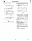
vee 0
c~1
c,
I~
TYPICAL
POWER-ON
RESET
RC
VALUES'
Rl =
75Kn
Cl
=1
!iF
'VALUES
MAY
HAVE
TO
VARY
DUETO
APPLIED
POWER
SUPPLY
RAMP
UP
TIME.
Figure
3.
Power-On Reset Circuit
6-12
AFN·01835C
i1
\1"
I
:1