


APPLICATION EXAMPLE 3
CASSETTE
RECORDER
INTERFACE
There are many situations where data has to be
transmitted through a non-ideal medium.
To
give
three typical examples, a system with electrically
isolated elements might require
that
signals be
AC
coupled, communications through an audio net-
work (such
as
telephone
or
radio) are greatly band-
width limited, and some applications (such
as
a
distributed network in an industrial environment)
must tolerate
random
electrical noise.
Attempting
to
record data
on
a cheap cassette recorder (the
one
used for this note cost
$17.00)
will reveal all
of
these shortcomings, plus one: The tape speed
fluctuates significantly and varies
as
the batteries
fun down, hence
the
data
rate
is
inconsistent.
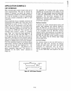
The recording scheme used here makes very few
demands on the transmission medium.
It
makes no
attempt
to transmit
DC
voltage levels. Instead, data
is
transmitted
by
a series
of
variable length tone
bursts. The
dominant
frequency
of
the tone used
can be selected
to
be within
the
passband
of
the
particular medium. Data
is
transmitted with each
bit composed
of
a
tone
burst followed by a pause.
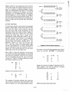
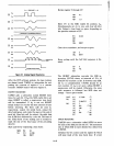
The first third
of
a bit period
is
always a tone
burst, the middle third
is
either
a tone burst con-
tinuous
with
the
first
or
a pause corresponding
to,
respectively, a one
or
zero, and the final third
is
always a pause, as shown in Figure 25. Thus,
data
is distinguished
by
the
burst/pause
ratio.
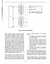
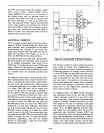
Hardware Design
These tone bursts are obtained from the 8085
SOD
line, using analog signal conditioning
to
eliminate
the DC
component
of
the waveform. (This low
frequency
component
is
due to the single-ended
nature
of
the SOD line:
it's
deviations from ground
are all positive, which unbalances the capacitive
input
stage
of
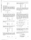
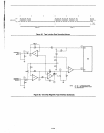
the recorder.) A suggested interface
A1-38
circuit
is
shown in Figure 26, using
one
LM324
quad
op amp and a few
standard
value discrete
components
which should be available
in
even a
digital design laboratory.
On playback, analog cir-
cuitry
is
again used to
detect
the
presence
of
a tone
burst. In Figure 26, A2 buffers
the
incoming signal,
and A3 inverts it. The peaks
of
these
two
signals
are transmitted through
0 I
or
02
and are filtered
by an RC network.
Comparator
A4 then squares
up the
output
and produces the logic signal read
by
the
SID pin. Since
the
op
amps are powered
by
the
single 5-volt supply, a 2.0-volt reference level
is
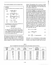
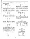
obtained from a resistive voltage divider. The
waveforms present at several points in
the
circuit
are shown in Figure 27.
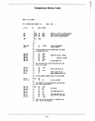
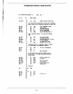
Software
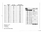
The algorithm for reading a data
bit
off
the
tape
is
simple and straightforward:
If
the
tone
burst
is
longer
than
the
pause, the bit is a one. Otherwise,
it
is
a zero. Since only the time
ratio
is
considered,
any variation in tape speed will
not
affect
the
data
determination.
VOLUME CONTROL
A
question
that
arises with
any
audio
cassette
inter-
face
is
how
to
set
the
volume
control.
(Recording
level
is
usually
determined
internally.)
When
the
play-
back level
is
correct.
the
logk
signal
output
from
A4
will have
either
a
one-third
or
two-thirds
du
ty cycle.
This
can
be readily observed
with
an oscilloscope. In
the
field, an
old-fashioned
mechanical-type
voltmeter
could
be
connected
to
the
A4
output,
and
the
volume
adjusted
until
the
mete~
needle
hovered
somewhere
between
1/3
and
2/3
the
high level
output
voltage.
With
random
data,
the
reading
would
be
about
2
volts.
There
will be a fairly wide range
of
acceptable
volume
settings.
(Since
the
quivering
meter
needle
is
being used here
for
inertial signal averaging, a digital
voltmeter
would
not
be very
helpful
in
this
applica-
tion.)