APPLICATION EXAMPLE 1
MINIMUM
SYSTEM APPLICATION
AS
A TEMPERATURE SENSOR
Overview
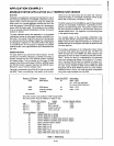
Following is an application example that illustrates the use of
the interrupt and
SOD pins on the 8085A, software for a block
search routine, and the procedure for using and reading the
8155 counter.
It
is a simple application showing the use of the
small but powerful 3-chip MCS-85 system as a temperature
sensor (SDK-85 board used). This example can be modified
to be
an
accurate industrial temperature controller, for several
locations if desired.
The basic operation behind this application is a monostable
multivibrator having its timing
pulse duration controlled by a
thermistor. The counter in the
8155
converts this timing pulse
to a decimal count that is software mapped into a temperature
and displayed
in
degrees C
in
the address field of the display
in the .SDK-85 Kit. For the purpose of keeping the software
relatively simple, many approximations were incorporated into
the code.
Detailed Hardware
The basic SDK kit was used for the initial hardware. This Kit
provides for everything necessary to develop and debug a
program through the use of the SDK-85 monitor, keyboard
and display board. The kit provides for 256 bytes of RAM
resident in the 8155 and 2K bytes of
ROM or EPROM where
the SDK-85 monitor is placed. (See the
Intel SDK-85 User's
Manual for copy of monitor software code.)
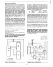
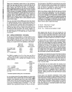
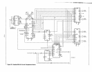
Figure
20
is a schematic of the SDK-85 Kit with only one 8155
and 8355. There is no buffering
in
this system as all compo-
nents are on the same board and far
below the maximum
component loading. A monostable multivibrator
(74121)
is also
shown with a thermistor connected to RE/CE.
The
SOD output pin from the B085A is used for the purpose
of
starting the monostable multivibrator in generating its tem-
perature controlled timing pulse. This pulse is created by the
RC
time constant provided for by the thermistor acting as a
variable resistor and a
.1
J.lF
capacitor to put the timing pulse
in the desired timing range.
The inverted output of the monostable multivibrator (one
shot) has been directly connected to the RST 6.5 pin
on
the
8085A. Since this pin is high level sensitive, it is necessary to
disable interrupts
in
the program until after the pulse from the
one shot goes
low.
The hardware addressing
in
the configuration shown allows
for several code spaces that could be used. The RST and
TRAP interrupt
lines on the 8085A also have hardware start
addresses but many of these are altered by the SDK monitor.
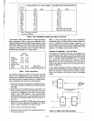
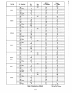
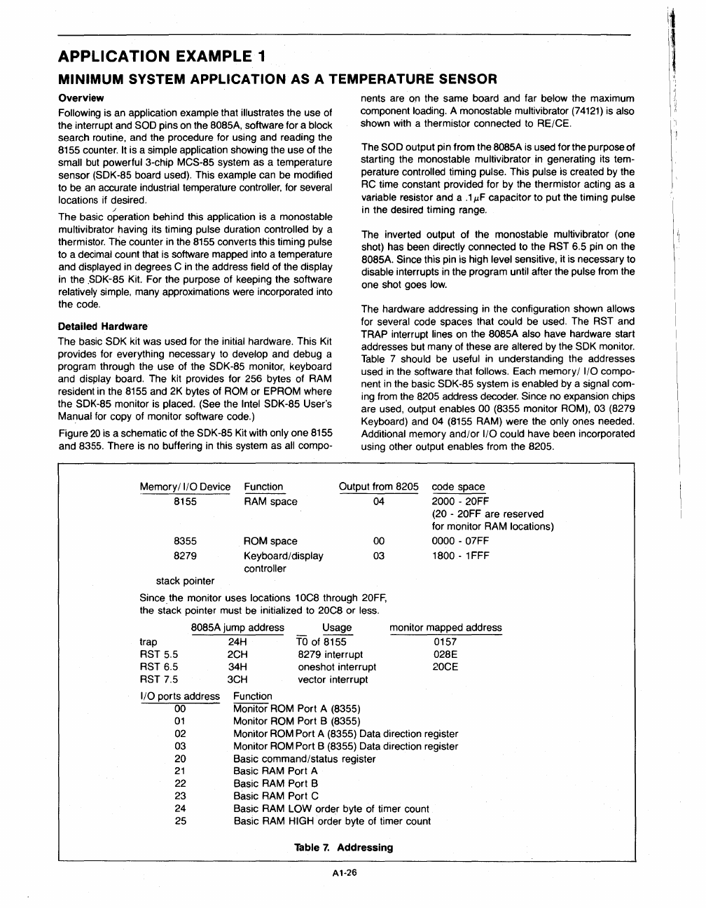
Table 7 should
be
useful in understanding the addresses
used
in
the software that follows. Each memory/ I/O compo-
nent
in
the basic SDK-85 system is enabled by a signal com-
ing from the 8205 address decoder. Since no expansion chips
are used, output enables
00 (8355 monitor ROM), 03 (8279
Keyboard) and
04
(8155
RAM) were the only ones needed.
Additional memory and/or
I/O could have been incorporated
using other output enables from the
8205.
Memory/ I/O Device
Function
Output from 8205
code space
8155 RAM space
04 2000 - 20FF
(20
- 20FF are reserved
for monitor RAM locations)
8355
ROM space 00 0000 - 07FF
8279 Keyboard/display 03
1800
- 1 FFF
controller
stack pointer
Since
the
monitor uses locations 10C8 through
20FF,
the stack pointer must be initialized to 20C8 or less.
8085A
jump address Usage monitor mapped address
0157 trap
RST 5.5
RST 6.5
RST 7.5
I/O ports address
00
01
02
03
20
21
22
23
24
25
24H
TO
of 8155
2CH 8279 interrupt
34H oneshot interrupt
3CH vector interrupt
Function
Monitor
ROM Port A (8355)
Monitor
ROM Port B (8355)
028E
20CE
Monitor ROM Port A (8355) Data direction register
Monitor
ROM Port B (8355) Data direction register
Basic command/status register
Basic RAM Port A
Basic RAM Port B
Basic RAM Port
C
Basic RAM LOW order byte of timer count
Basic RAM
HIGH order byte of timer count
Table
7.
Addressing
A1-26


