


The CRT and Cassette Code also includes a simple
block record routine utilizing T
APEO. Before
calling BLKRCD,
HL
must be set to the start
of
the desired block, and the recorder turned on
manually. Successive bytes
will
be recorded until
the end
of
that
page, i.e., until L
is
incremented
to
zero. The playback routine requires presetting HL
to
the target address and turning on the recorder
before
PLA
YBK
is
called. These routines incorpor-
ate a long tone burst before each data block to
allow a recorder with Automatic Gain Control
to
stabilize before the data starts.
ADDITIONAL
COMMENTS
The two design examples given
so
far were built up
using an
SDK-85 System Design Kit. Both hard-
ware interfaces were wire-wrapped on the ample
breadboarding area provided on the board. The
connections between
SID
and
SOD
and the on-
board
TTY interface were broken, so
as
not
to
affect the 8085
1/0
electrical characteristics.
The CRT interface was tested with a Beehive
Mini-
Bee
II
Terminal in the full duplex mode at each
of
its
14
possible transmission rates, from 110 to
9600 baud.
It
was also checked out at 19200 baud
using a Beehive
B-IOO
terminal. In addition, the
software was exercised using an
SBC
80/20
system
as
a variable baud rate character generator and
receiver.
An
additional advantage to having software select-
able communications rates
is
that
it
would be pos-
sible
to
communicate with several system periper-
als;
each at its own preferred rate, without having
to
duplicate hardware.
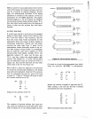
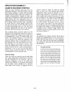
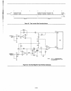
For
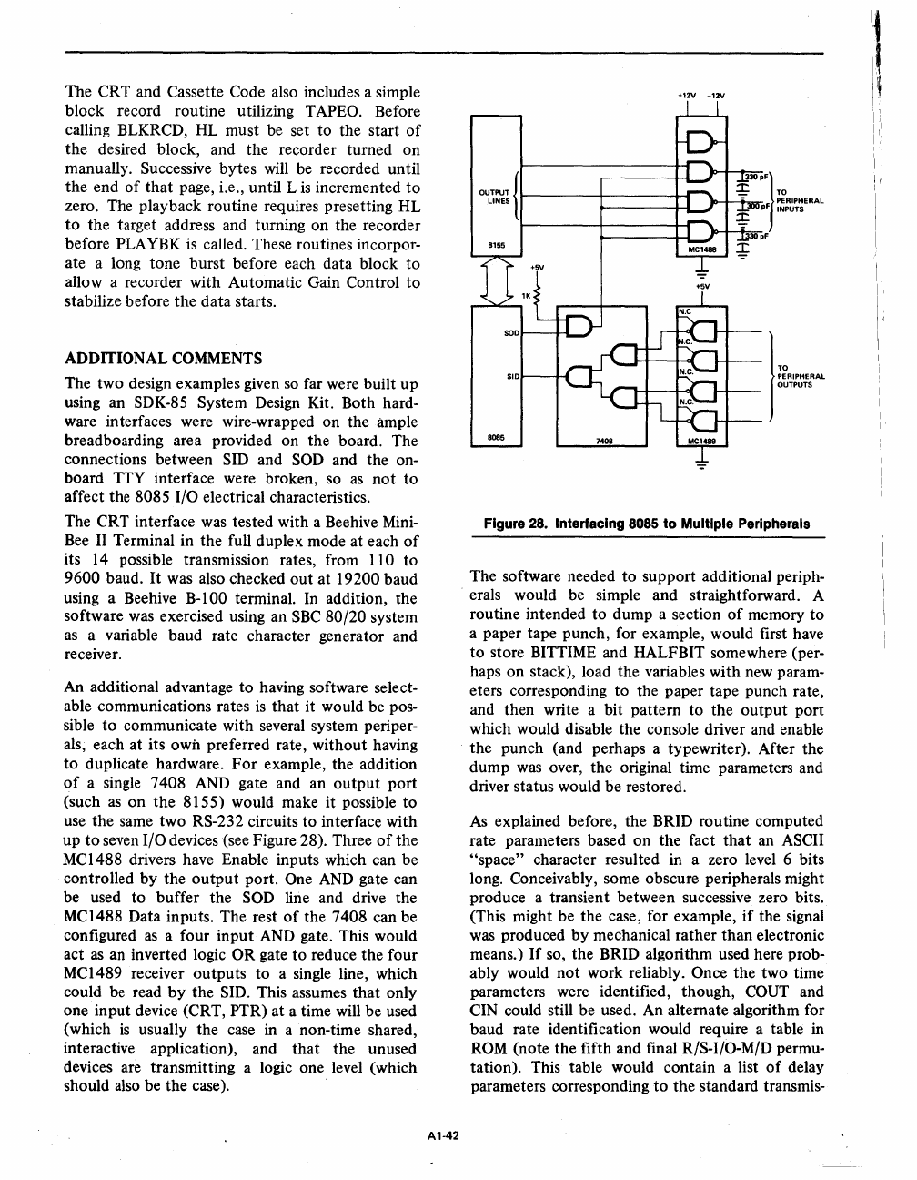
example, the addition
of
a single 7408
AND
gate and an output port
(such
as
on the 8155) would make it possible
to
use the same two RS-232 circuits to interface with
up
to
seven I/O devices (see Figure 28). Three
of
the
MC1488 drivers have Enable inputs which can be
controlled by the
output
port. One
AND
gate can
be used to buffer the
SOD
line and drive the
MC1488 Data inputs. The rest
of
the 7408 can be
configured
as
a four input
AND
gate. This would
act
as
an
inverted logic OR gate to reduce the four
MC1489 receiver outputs to a single line, which
could
be
read
by
the
SID.
This assumes that only
one input device (CRT, PTR) at a time will be used
(which
is
usually the case
in
a non-time shared,
interactive application), and that the unused
devices are transmitting a logic one level (which
should
also
be the case).
A1-42
+12V
-12V
8085
7408 MCl489
I
TO
PERIPHERAL
OUTPUTS
Figure
28.
Interfacing
8085
to
Multiple Peripherals
The software needed to support additional periph-
erals would be simple and straightforward. A
routine intended to dump a section
of
memory
to
a paper tape punch, for example, would first have
to
store BITTIME and HALFBIT somewhere (per-
haps on stack), load the variables with new param-
eters corresponding to the paper tape punch rate,
and then write a bit pattern to the output port
which would disable the console driver and enable
the punch (and perhaps a typewriter). After the
dump
was
over, the original time parameters and
driver status would be restored.
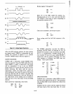
As explained before, the BRID routine computed
rate parameters based on the fact that an
ASCII
"space"
character resulted in a zero level 6 bits
long. Conceivably, some obscure peripherals might
produce a transient between successive zero bits.
(This might be the case, for example,
if
the signal
was
produced by mechanical rather than electronic
means.)
If
so, the BRID algorithm used here prob-
ably would not work reliably.
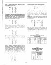
Once the two time
parameters were identified, though,
COUT
and
CIN could still be used. An alternate algorithm for
baud rate identification would require a table in
ROM
(note the fifth and final
RIS-I/O-M/D
permu-
tation). This table would contain a list
of
delay
parameters corresponding
to
the standard transmis-