


8085AH/8085AH-2/8085AH-1
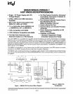
FUNCTIONAL DESCRIPTION
The 8085AH
is
a complete 8-bit para"el central pro-
cessor.
It is designed with N-channel, depletion
load, silicon gate technology
(HMOS), and requires
a single
+5
volt supply. Its basic
clock
speed
is
3 MHz (8085AH), 5 MHz (8085AH-2),
or
6 MHz
(8085AH-1), thus improving on the present 8080A's
performance with higher system speed. Also
it
is
designed
to
fit
into a minimum system
of
three IC's:
The
CPU
(8085AH), a RAM/IO (8156H), and a
ROM
or
EPROM/IO chip (8355
or
8755A).
The
8085AH has twelve addressable 8-bit registers.
Four
of
them can function only
as
two 16-bit register
pairs.
Six others can
be
used interchangeably
as
8-bit registers
or
as
16-bit register pairs. The 8085AH
register set is as follows:
Mnemonic
Register
Contents
ACC
or
A
Accumulator
8 bits
PC
Program Counter
16-bit address
BC,DE,HL
General-Pu rpose 8 bits x 6
or
Registers; data
16bitsx3
pointer
(HL)
SP
Stack
Pointer
16-bit address
Flags
or
F
Flag Register
5
flags (8-bit space)
The 8085AH uses a multiplexed Data Bus. The
address
is
split between the higher 8-bit Address
Bus and the lower 8-bit Address/Data Bus. During
the first T state (clock cycle)
of
a machine cycle the
low order address
is
sent out on the Address/Data
bus. These
lower 8 bits may
be
latched externally by
the Address Latch Enable signal (ALE). During the
rest
of
the machine cycle the data bus is used for
memory
or
I/O
data.
The
8085AH provides
RD,
WR,
So,
S1,
and
101M
signals
for
bus control. An Interrupt Acknowledge
signal
(INTA) is also provided. HOLD and
a"
Inter-
rupts are synchronized with the processor's internal
clock. The
8085AH also provides Serial Input Data
(SID) and Serial Output Data
(SOD)
lines
for
simple
serial interface.
In addition to these features, the 8085AH has three
maskable, vector interrupt pins, one nonmaskable
TRAP interrupt, and a bus vectored interrupt,
INTR.
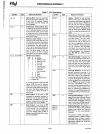
INTERRUPT AND SERIAL
1/0
The 8085AH has 5 interrupt inputs: INTR, RST
5.5,
RST
6.5,
RST
7.5, and
TRAP.
INTR
is
identical in
function
to
the 8080A
INT.
Each
of
the three
RE-
START inputs, 5.5,6.5, and 7.5, has a programmable
mask. TRAP is also a
RESTART interrupt but it
is
nonmaskable.
6-13
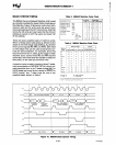
The three maskable interrupts cause the internal
execution
of
RESTART (saving the program counter
in the stack and branching to the RESTART address)
if
the interrupts are enabled and
if
the interrupt mask
is not set. The nonmaskable TRAP causes the inter-
nal execution
of
a RESTART vector independent
of the state
of
the interrupt enable
or
masks. (See
Table
2.)
There are two different types of inputs in the restart
interrupts.
RST 5.5 and
RST
6.5 are
high
leve/-
sensitive like
INTR (and INT on the 8080) and are
recognized with the same timing as
INTR.
RST
7.5
is
rising edge-sensitive.
For
RST
7.5,
only a pulse is required to set
an
inter-
nal flip-flop which generates the internal interrupt
request
(a
normally high level signal with a low
going pulse
is
recommended
for
highest system,
noise immunity). The
RST 7.5 request
flip-flop
remains set
until
the request is serviced. Then
it
is
reset automatically. This flip-flop may also be
reset by using the SIM instruction
or
by issuing a
RESET
IN
to the 8085AH. The
RST
7.5 internal flip-
flop
wi"
be set by a pulse on the
RST
7.5 pin even
when the
RST
7.5 interrupt
is
masked out.
The status
of
the three
RST
interrupt masks can only
be
affected by the SIM instruction and RESET
IN.
(See SIM,
Chapter
5
of
the
MCS-80/85 User's
Manual.)
The interrupts are arranged in a fixed priority that
determines which interrupt is
to
be
recognized if
more than one is
pending
as
follows:
TRAP-
highest priority,
RST
7.5,
RST
6.5,
RST
5.5,
INTR-
lowest priority. This priority scheme does not take
into account the priority
of
a routine that was started
by a higher priority interrupt.
RST
5.5 can interrupt
an
RST
7.5
routine
if
the interrupts are re-enabled
before the end
of
the RST
7.5
routine.
The TRAP interrupt is useful
for
catastrophic events
such
as
power failure
or
bus error. The TRAP input is
recognized just
as
any other interrupt but has the
highest priority.
It is
not
affected by any flag
or
mask.
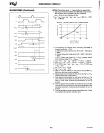
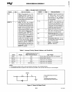
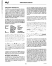
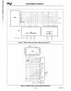
The TRAP input is both edge and level sensitive. The
TRAP input must go high and remain high until it is
acknowledged.
It will not be recognized again until
it
goes low, then high again. This avoids any false
triggering due
to
noise
or
logic glitches. Figure 4
illustrates the TRAP
interrupt
request
circuitry
within the 8085AH. Note that the servicing
of
any
interrupt
(TRAP,
RST
7.5,
RST
6.5,
RST
5.5,
INTR)
disables
a"
future interrupts (except TRAPs) until
an
EI
instruction
is
executed.
AFN·01835C