


INTERRUPT
SEQUENCES
The
8080
has
the
built-in capacity
to
hand
Ie
external
interrupt
requests. A peripheral device can initiate an inter-
rupt
simply
by driving
the
processor's
interrupt
(lNT) line
high.
The
interrupt
(INT)
input
is
asynchronous,
and
a
request
may
therefore
originate
at
any
time
during
any
instruction
cycle. I nterna I logic re-clocks
the
external
re-
quest,
so
that
a
proper
correspondence
with
the
driving
clock
is
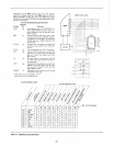
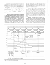
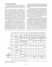
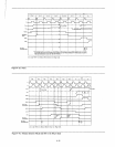
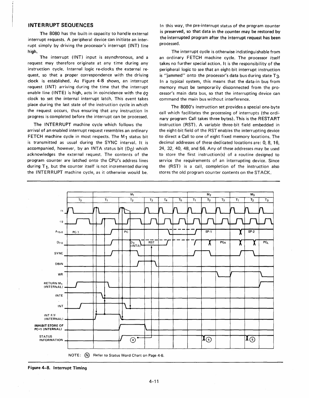
established. As Figure
4-8
shows,
an
interrupt
request
(INT) arriving during
the
time
that
the
interrupt
enable
line (INTE)
is
high,
acts
in
coincidence
with
the
¢2
clock
to
set
the
internal
interrupt
latch. This event
takes
place
during
the
last state
of
the
instruction
cycle
in
which
the
request
occurs,
thus
ensuring
that
any
instruction
in
progress
is
completed
before
the
interrupt
can be processed.
The
INTERRUPT
machine cycle
which
follows
the
arrival
of
an
enabled
interrupt
request
resembles
an
ordinary
FETCH machine cycle
in
most
respects.
The
M 1
status
bit
is
transmitted
as usual during
the
SYNC interval. It
is
accompanied,
however,
by
an INTA
status
bit
(DO)
which
acknowledges
the
external
request.
The
contents
of
the
program
counter
are latched
onto
the
CPU's address lines
during
T 1,
but
the
counter
itself
is
not
incremented
during
the
INTERRUPT
machine cycle, as it
otherwise
would
be.
Ml
T3
Tl
T2
T3
_h
Irn
r~
VL-
SYNC
DBIN
WR
RETURN
Ml
(INTERNAL)
INTE
INT
INT
F/F
(INTERNAL)
INHIBIT
STORE OF
PC+l
(INTERNAL)
STATUS
INFORMATION
-u---t
ur--L
pc·,
I
I
I
-w
\
\
-~
r-~
n
Ln
PC
~~TA}
RST
\
r
f--
1\
\
1\
1\
1/
0-
~
In
this
way,
the
pre-interrupt
status
of
the
program
counter
is
preserved, so
that
data
in
the
counter
may
be
restored
by
the
interrupted
program
after
the
interrupt
request
has been
processed.
The
interrupt
cycle
is
otherwise
indistinguishable
from
an
ordinary
FETCH
machine
cycle.
The
processor itself
takes
no
further
special
action.
It
is
the
responsibility
of
the
peripheral logic
to
see
that
an eight-bit
interrupt
instruction
is
"jammed"
onto
the
processor's
data
bus
during
state
T3.
In
a typical
system,
this
means
that
the
data-in bus
from
memory
must
be
temporarily
disconnected
from
the
pro-
cessor's main
data
bus, so
that
the
interrupting
device can
command
the
main bus
without
interference.
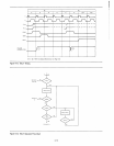
The
8080's
instruction
set
provides a special
one-byte
call which facilitates
the
processing
of
interrupts
(the ordi-
nary program Call
takes
three
bytes).
This
is
the
RESTART
instruction (RST). A variable
three-bit
field
embedded
in
the
eight-bit field
of
the
RST enables
the
interrupting
device
to
direct
a Call
to
one
of
eight fixed
memory
locations.
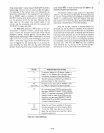
The
decimal addresses
of
these
dedicated
locations
are:
0,8,
16,
24, 32, 40,
48,
and
56.
Any
of
these
addresses
may
be used
to
store
the
first
instruction
(s)
of
a
routine
designed
to
service
the
requirements
of
an
interrupting
device. Since
the
(RST)
is
a call,
completion
of
the
instruction
also
stores
the
old program
counter
contents
on
the
STACK.
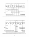
M2 M3
T4
Ts
Tl
T2
T3
Tl
T2
T3
n-
n-n-
rL-rL-
n-
~
rL-
Ln
Ln Ln Ln Ln
Ln
U\.
Lf1
---
~
J
\
sp·,
X
SP·2
-7
ro--
~
1..
PCti
X
X
PCL
r
1\
.r
\
1'--'
L-
r-
I
l
0
I
X
0
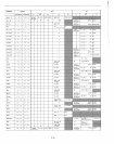
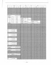
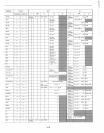
NOTE: ®
Refer
to
Status
Word
Chart
on Page 4-6.
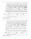
Figure 4-8_
Interrupt
Timing
4-11