


THE
INSTRUCTION SET
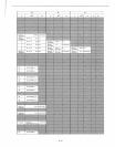
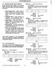
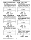
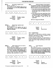
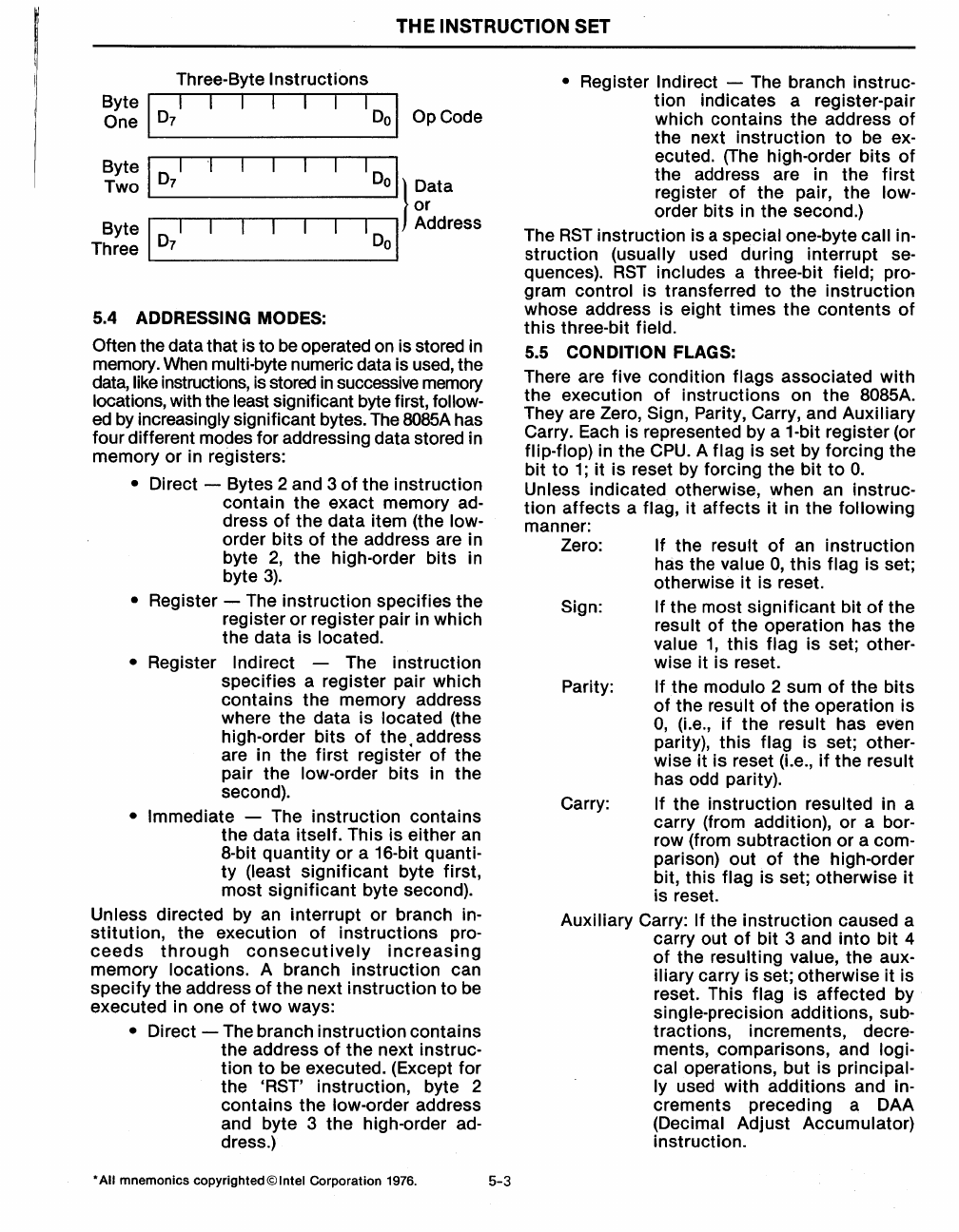
Three-Byte Instructions
Byte I I I I I I I I 0 I
One . 0
7
O.
Op Code
Byte
1
0
I I I
Two.
7
Do
} Data
L-
_________
---I
or
Byte
l_I
________
I_D---JO
I Address
Three
0
7
.
5.4 ADDRESSING MODES:
Often
the data that is to
be
operated on is stored in
memory.
When
multi-byte numeric data is used, the
data,
like instructions, is stored
in
successive memory
locations, with the least significant byte first, follow-
ed
by increasingly significant bytes.
The
8085A
has
four different modes for addressing data stored in
memory
or
in registers:
• Direct - Bytes 2 and 3
of
the instruction
contain the exact memory
ad-
dress
of
the data item (the low-
order
bits
of
the address are in
byte
2,
the high-order bits in
byte
3).
• Register - The instruction specifies the
register
or
register pair in which
the data is
located.
•
Register Indirect - The instruction
specifies a register pair which
contains the memory address
where the
data
is located (the
high-order
bits
of
the.
address
are in
the
first
register
of
the
pair the
low-order bits in the
second).
• Immediate - The instruction contains
the data
itself. This is either an
8-bit quantity
or
a 16-bit quanti-
ty
(least
significant
byte first,
most
significant
byte second).
Unless directed by an interrupt
or
branch in-
stitution,
the execution
of
instructions
pro-
ceeds
through
consecutively
increasing
memory locations. A branch instruction can
specify
the address
of
the next instruction
to
be
executed in one
of
two
ways:
• Direct - The branch instruction contains
the address
of
the
next instruc-
tion
to
be executed. (Except for
the
"RST'
instruction, byte 2
contains the
low-order address
and byte 3 the high-order
ad-
dress.)
*AII mnemonics
copyrighted©lntel
Corporation 1976.
5-3
• Register Indirect - The branch instruc-
tion indicates a register-pair
which contains
the
address
of
the next instruction
to
be ex-
ecuted. (The high-order
bits
of
the address are in the
first
register
of
the pair, the low-
order bits in the second.)
The
RST
instruction is a special one-byte call in-
struction (usually used during interrupt se-
quences).
RST
includes a three-bit field; pro-
gram control is transferred
to
the
instruction
whose address is eight
times
the
contents
of
this
three-bit field.
5.5
CONDITION FLAGS:
There are five condition
flags associated
with
the execution
of
instructions on
the
8085A.
They are
Zero, Sign, Parity, Carry, and Auxiliary
Carry. Each is represented by a 1-bit register (or
flip-flop) in the
CPU.
A flag is set by forCing the
bit
to
1;
it is reset by forCing
the
bit
to
O.
Unless indicated otherwise, when an instruc-
tion
affects
a flag, it
affects
it in the following
manner:
Zero:
Sign:
Parity:
If the result
of
an instruction
has the
value
0,
this
flag is set;
otherwise
it
is reset.
If the most
significant
bit
of
the
result of the operation has
the
value
1,
this
flag is set; other-
wise it is reset.
If the modulo 2 sum
of
the
bits
of
the result
of
the operation is
0,
(Le.,
if
the result has even
parity),
this
flag is set; other-
wise it
is
reset (Le.,
if
the result
has odd parity).
Carry:
If the instruction resulted in a
carry (from addition), or a
bor-
row (from subtraction
or
a com-
parison) out
of
the
high-order
bit, this
flag is set; otherwise it
is reset.
Auxiliary Carry: If the
instruction
caused a
carry out
of
bit 3 and
into
bit 4
of
the resulting value, the aux-
iliary carry is set; otherwise it is
reset. This
flag is affected by
single-precision additions, sub-
tractions, increments, decre-
ments, comparisons, and
logi-
cal
operations, but is principal-
ly
used with
additions
and in-
crements preceding a DAA
(Decimal Adjust Accumulator)
instruction.