


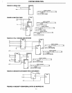
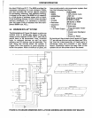


SYSTEM OPERATION
3.9
EXPANDED
MCS·85™
SYSTEM
Figure
3.8
shows the
circuit
Figure 3.6 ex·
panded
to
its
maximum size
without
the use
of
any extra logic. In an extremely small board
area we can fit:
PARTS FUNCTION
18085A
3 8355/8755A
28156
1 Crystal
4 Resistors
1 Capacitor
1 Diode
1
CPU
(Clock cycle
~
320ns) .
ROM/EPROM
6144 Bytes
512
Bytes
RAM
76
110
Lines
5
Interrupts
2 Programmable
Timer/Counters
2
Serial
110
Lines
1
Crystal and
Oscillator
1 Clock
1 Power·on Reset
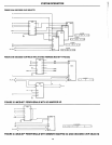
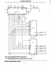
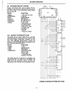
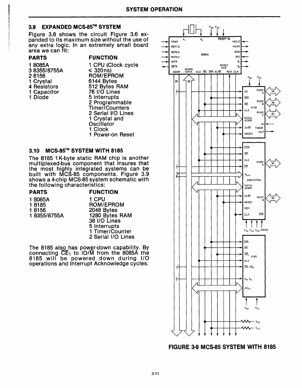
3.10
MCS·85™
SYSTEM WITH 8185
The 8185 1 K-byte
static
RAM
chip is another
multiplexed-bus component that insures
that
the most highly integrated systems can
be
built
with
MCS-85
components.
Figure 3.9
shows a 4-chip
MCS-85 system schematic with
the
following characteristics:
PARTS FUNCTION
18085A 1
CPU
1 8185 ROM/EPROM
1 8156 2048 Bytes
1 8355/8755A
1280 Bytes
RAM
38
I/O Lines
5
Interrupts
1 Timer/Counter
2
Serial I/O Lines
The 8185
alsJLhas
pow~r-down
capability.
By
connecting
CE1
to
10/M from the 8085A the
8185
will
be
powered
down
during
I/O
operations and Interrupt Acknowledge cycles.
3-11
_ TRAP
X,
x,
~
HOLD _
_ RST7,S
HlDA
~
- RST6,S 808SA SOD
~
_
RSTS,S
SID
I-
- INTR S, f----
_ INTA
R6~~T
So
f----
ADDR
-m.~~1
ALE
AD
WR
101M
ROY
ClK
(8)
Y
T
vr
c+-
t+-
Ie-+-
+-+-I--\--+~--+--+-.I
~
PORr
KV
~+----l-+--+--+-+-I
;:
POR~
~
I A
II'\.
ALE 8156
POR~
~
V·L.L.-.l..-....J'--1.--L.---'-....JJ-
'\
DATAl
Iy::;.v
I
"-"
....---.---,---.---,--r--n- / ADDR
~
IV
IN~
""'_+--I---+-IIO/M
TIMER
'-+---i-I
RESET OUT
t--
~I-+-+--+-·IIOW
.....-t--I-+-+-t-+-I
AD
~+---1I--1-+-+-I-+-1
ALE
1---1-1--1--1-4-+-+-
CE
1--...........,r---r---,---,--,-......,....,,/1
AB.,o
I.
• 83SS/87SSA
(L.L.-.l..-....Ji-...J..----L..---'--.lJ..u",
OAT AI
:
~rr-,--,r-r--,----.--ny
ADDR
101M
KV
POR~
(8)
....._-1---1-1
RESET
ROY
.......
ClK
fOR
t t t t
Vss
Vee
V
DD
PROG
'-~-+--+-+-I
WR
....._t---ir--+-+-I--t
AD
~+---1I-+-+-+-I-+-1
ALE
I---+-I--I--+-+--+--+-+-I
CS.
CE,
A
B
•
A9
>
ADo.,
t
Vss
,AA
~AA
yv
t
Vee
Vee
Vee
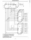
FIGURE
3·9
MeS·85
SYSTEM
WITH
8185