


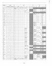

THE INSTRUCTION SET
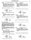
PC
SP
LABEL
s
p
~y
1\
+
\JNN
16-bit
program
counter
register (PCH and
PCl
are
used
to
refer
to
the high-order
and low-order 8
bits
respec-
tively).
16-bit
stack
pointer register
(SPH
and
SPl
are used
to
refer
to
the high-order and low-order
8
bits
respectively).
Bit m
of
the register r (bits are
number 7 through 0 from left
to
right).
16-bit address
of
subroutine.
The
condition
flags:
Zero
Sign
Parity
Carry
Auxiliary Carry
The
contents
of
the memory
location
or
registers enclosed
in
the parentheses.
"Is
transferred
to"
logical
AND
Exclusive
OR
Inclusive OR
Addition
Two's
complement
subtraction
Multiplication
"Is
exchanged
with"
The one's complement (e.g.,
(A))
The restart number 0 through 7
The binary representation 000
through
111
for restart number
o through 7 respectively.
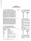
rhe
instruction
set encyclopedia is a detailed
jescription
of the 8085A
instruction
set. Each
nstruction
is described in the
following
man-
ler:
I. The MCS-85 macro assembler format, con-
sisting
of
the
instruction
mnemonic and
operand fields, is printed in BOLDFACE on
the
first
line.
~.
The name
of
the
instruction
is enclosed in
parentheses
following
the mnemonic.
3.
The next lines contain a
symbolic
description
of
what
the
instruction
does.
t This is followed by a narrative description
of
the operation
of
the
instruction.
All mnemonics copyrighted © Intel Corporation 1976.
5-2
5.
The boxes describe the binary codes
that
comprise
the machine
instruction.
6.
The last four lines contain
information
about
the execution
of
the
instruction.
The number
of
machine cycles and
states
required
to
ex-
ecute
the
instruction
are listed first. If the in-
struction
has
two
possible
execution
times,
as in a
conditional
jump, both
times
are
listed, separated by a slash. Next,
data
ad-
dressing modes are listed
if
applicable. The
last
line
lists
any
of
the five
flags
that
are af-
fected
by the execution
of
the
instruction.
5.3 INSTRUCTION AND DATA FORMATS
Memory used in the MCS-85
system
is organ-
ized
in
8-bit bytes.
Each
byte has a unique location
in
physical memory. That location is described
by
one of
a sequence of
16-bit
binary addresses. The
8085A
can
address up
to
64K
(K
= 1024, or 2
10
; hence, 64K
represents the decimal number 65,536) bytes
of
memory, which may consist of both random-access,
read-write memory (RAM) and read-only memory
(ROM),
which
is also random-access.
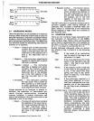
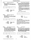
Data in the 8085A is stored in
the
form
of
8-bit
binary integers:
DATA WORD
I
I I I I I I I I
0
7
0
6
0
5
0
4
0
3
O
2
0
1
Do
MSB
lSB
When a register
or
data
word
contains
a binary
number,
it is necessary to establish the order
in
which
the bits of the number
are
written.
In
the Intel
8085A,
BIT
0 is referred to as the Least Significant Bit
(LSB),
and BIT 7 (of an 8-bit number) is referred
to
as the
Most
Significant
Bit
(MSB)_
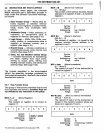
An
8085A program instruction may be one,
two
or
three bytes
in
length. Multiple-byte instructions must
be
stored
in
successive memory locations; the address
of the first byte
is
always
used
as
the address of the
in-
struction. The exact instruction format will depend
on
the
particular
operation
to
be executed.
Single Byte
Instructions
I
I I I I I I I I
0
7
Do
Op Code
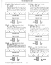
Two-Byte
Instructions
Byte I 0 I I 0 I Data
or
Two 7 0 Address
~--------------------~
II
I