


February 2002 © TOSHIBA TEC 1 - 9 FC-210/310
ERROR CODES AND SELF-DIAGNOSIS
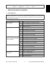
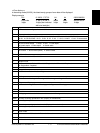
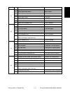
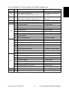
Digital key Icon Item Condition
A Bypass paper-width sensor 0 Refer to Table 1.
B Bypass paper-width sensor 1 Refer to Table 1.
C Bypass paper-width sensor 2 Refer to Table 1.
[5]
D —
E Bypass paper sensor 1: No paper
F Bypass unit open/close switch 1: Unit is opened.
G Side door open/close switch 1: Side door is opened.
H Bypass unit is installed or not 0: Unit is installed.
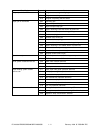
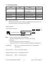
A LCF paper-empty sensor 1: No paper
B LCF lower-limit sensor 1: Tray limit (lower)
C LCF tray-up sensor 1: Tray limit (upper)
[6]
D LCF tray-down switch 0: Switch is ON.
E LCF paper supply door sensor 1: Door is opened.
F LCF is installed or not 0: LCF is installed.
G ADU motor rotation status 0: Normal rotation
(Motor is rotating by output check 03)
H ADU is installed or not 0: ADU is installed.
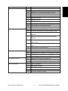
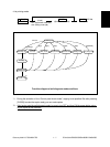
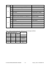
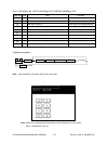
A ADU paper-jam sensor 1: Paper present
B ADU paper-empty sensor 0: No paper
C ADU end switch 1: End guide is at home position.
[7]
D ADU side switch 1: Side guide is at home position.
E —
F —
G Key copy counter is installed or not 0: Key copy counter is installed.
H —
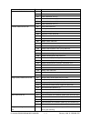
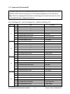
A Developer removal shutter home position sensor 0: Shutter is at closed position.
B —
C Transfer belt unit is installed or not 0: Unit is installed.
D —
[8]
E —
F Developer motor rotation status 0: Normal rotation
(Motor is rotating by output check 03)
G Transfer belt limit switch 0: Transfer belt is in black mode position.
H Transfer belt home position switch 0: Transfer belt is in color mode position.