


FC-210/310 ADJUSTMENT 2 - 30 February 2002 © TOSHIBA TEC
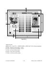
2.7 High-Voltage Transformer Settings
2.7.1 Overview
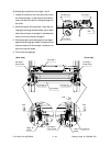
This machine uses four main high-voltage transformers for charging/development/discharging and one
transfer transformer for transfer/suction.
The main high-voltage transformers (PS-HVT-M-314) are used each for one of the colors Y, M, C and K,
giving a total of four units.
The transfer transformer (PS-HVT-TB-310) supplies high-voltage for the transfer rollers Y, M, C and K and
the suction charger to be used in black mode.
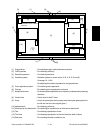
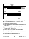
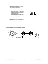
The main high-voltage transformers have the following high-voltage outputs.
CH1: main charger wire
CH2: main charger grid bias
CH3: developer bias
CH4: cleaning blade bias
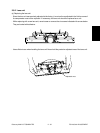
The transfer transformer has the following high-voltage outputs.
CH1: transfer roller bias (Y)
CH2: transfer roller bias (M)
CH3: transfer roller bias (C)
CH4: transfer roller bias (K)
CH5: suction charger
* CH5 is used in black mode only.
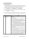
Note: The main high-voltage transformer and transfer transformer for service parts are supplied with the
data sheets to be used for the following setup. Be careful not to lose them.
Output adjustment is performed when the devices are shipped, so under any circumstances, do
not move the fixed volumes of resistors.
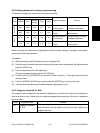
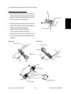
2.7.2 Settings after replacing main high-voltage transformers
After replacing a main high-voltage transformer, be sure to enter the data shown on the supplementary data
sheet (main charger grid bias and developer bias) according to the procedure below.
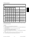
<Settings for main charger grid bias>
(1) Turn the power ON while pressing [0] and [5] simultaneously.
(2) Enter code 252 and press the [START] key.
ৎ The lower limit value for main charger grid bias is displayed for each Y, M, C and K.
(3) Enter the sub-code (0: Y, 1: M, 2: C, 3: K) and press the [START] key.
(4) Enter a value according to the supplementary data sheet and press the [SET] or [INTERRUPT] key.