


FC-210/310 POWER SUPPLY UNIT 6 - 2 February 2002 © TOSHIBA TEC
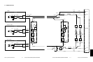
There are two output channels which are linked with the door switches.
(1) 5.1V(D) — For the laser diodes and the laser drivers
5.1VA : Pin 7, J702
Output to: LGC board
5.1VB : Pin 3, J705
Output to: IMC board, RLY board (via the IMC board), LDR board (via the IMC board)
(2) 24V(D) — For the motors, clutches, solenoids, fans, etc.
24VA~C :Pins 1, 2 and 3, J702
Output to: LGC board, paper feed motor (via the LGC board),
fuser motor (via the LGC board),
main high-voltage transformer (via the LGC board),
transfer transformer (via the LGC board)
24VD : Pins 1, 2 and 3, J703
Output to: developer motor
24VE : Pins 6 and 7, J703
Output to: paper feed motor
24VF : Pins 1 and 2, J704
Output to: SCM board
24VG : Pin 1, J705
Output to: IMC board, polygonal motor (via the IMC board), tilt motors (via the IMC board)
24VK : Pins 1, 3, 5, 7, 9, 11, 13, 15, 17 and 19, J711
Output to: LGC board
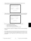
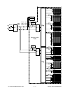
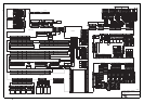
<Output connector>
Not linked with the door switch:
J706 for the LGC board
J707 for the IMC board, SYS board, RLY board and IMG board
J708 for the scanner and RADF
J709 for the finisher
J710 for the built-in printer controller (optional)
Linked with the door switch:
J702 for the LGC board
J703 for the developer motor and the paper feed motor
J704 for the scanner
J705 for the IMC board, RLY board, LDR board and the polygonal motor
J711 for the drum motors, the transfer belt motor and the LGC board