


C H A P T E R 11 Enterprise Standby Router Protocol (ESRP)
185
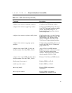
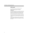
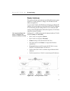
Figure 11.3 builds on Figure 11.4, but eliminates the requirement of
Layer 3 redundancy. It has these features:
• An additional VLAN, Engineering, is added that uses Layer 2
redundancy.
• The VLAN
Sales uses three active links to each upper switch.
• The VLAN
Engineering has two active links to each upper
switch.
• The switch labeled
Sales + Engineering carries traffic for both
VLANs.
• The link between the
Sales + Engineering switch and the Sales
master/Engineering standby
switch uses 802.1Q tagging to
carry traffic from both VLANs on one link. The switch counts the
link active for each VLAN.
• The
Sales standby/Engineering master switch has a separate
physical port for each VLAN connected to the third bottom
switch.
In this example, the master and standby switches are configured for
ESRP such that the VLAN Sales normally uses the first switch and
the VLAN Engineering normally uses the second switch. This is
accomplished by manipulating the ESRP priority setting for each
VLAN for the particular switch.
These are the configuration commands for the first switch (Sales
master/Engineering standby):
create vlan sales
configure sales tag 10
configure sales add port 1,2
configure sales add port 3 tagged
configure sales ipaddr 10.1.2.3/24
create vlan eng
configure eng tag 20
configure eng add port 4
configure eng add port 3 tagged
configure eng ipaddr 10.4.5.6/24
enable esrp sales
enable esrp eng
enable edp ports all
configure sales esrp priority 5
Configuration commands for the second switch (Sales standby/
Engineering master) are as follows: