C H A P T E R 18 Server Load Balancing (SLB)
379
Availability mode or having to introduce another interconnecting
switch), and recovery from a switch failure occurs in less than 8
seconds.
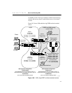
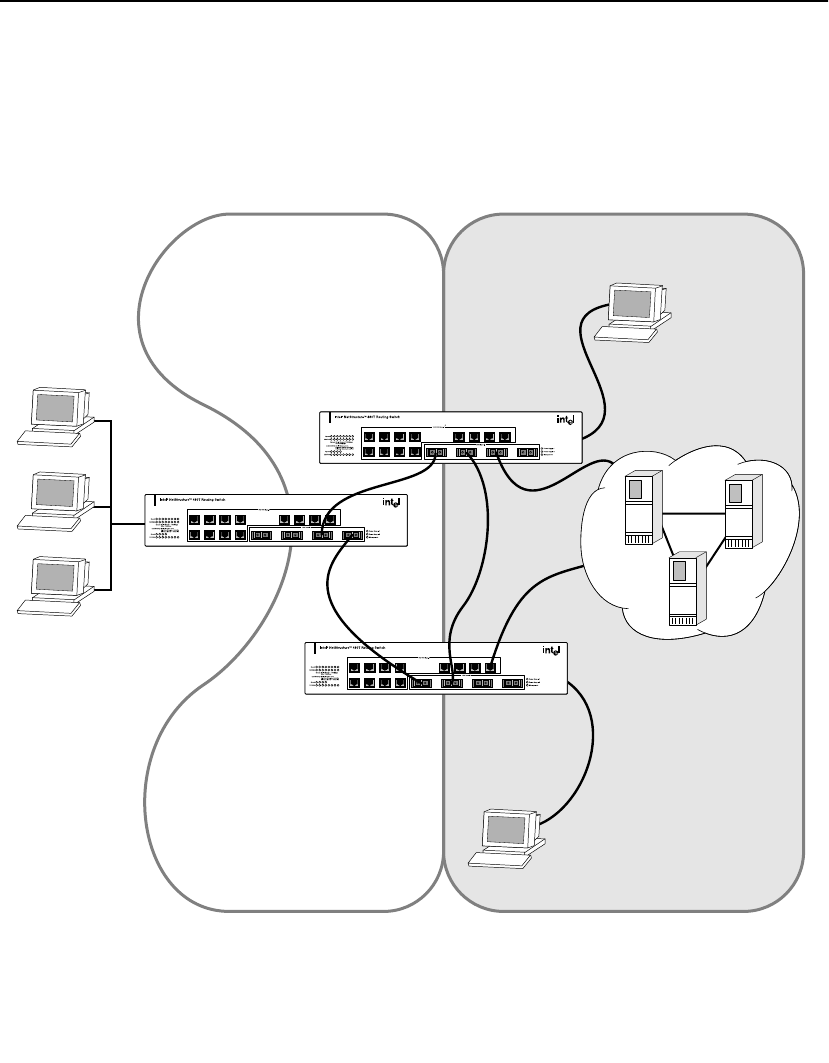
Figure 18.5 shows SLB enabled using ESRP and dual-attached
servers.
Figure 18.5: SLB using ESRP and dual-attached servers
3421
7865
11 12109
13 161514
87654321
161514131211109
Rx TxRx TxRx TxRx Tx
3421
7865
11 12109
13 161514
87654321
161514131211109
Rx TxRx TxRx TxRx Tx
3421
7865
11 12109
13 161514
87654321
161514131211109
Rx TxRx TxRx TxRx Tx
480T_058R
VLAN outside
1.201.0.1/16
Switch 1
VLAN inside
1.10.0.2/16
VIP site1 1.10.1.1 (switch)
VIP site2 1.10.1.2 (switch)
Switch 1
VLAN server
1.205.0.1/16
Switch 2
VLAN server
1.206.0.1/16
testpool
Real unique IP addresses
Server1 1.205.1.1/16
Server2 1.205.1.2/16
Server3 1.205.1.3/16
Server4 1.205.1.4/16
Associated VIPs
1.10.1.1 port 80 (site1)
1.10.1.2 port 80 (site2)
480T physical configuration
VLAN server
Dual-attached servers connected to ports 1-4
Interconnect (also configured as host) on port 32
VLAN inside
port 31 connects to gateway switch
480T physical configuration
VLAN outside
Dual-attached servers connected to ports 1-4
Interconnect (also configured as host) on port 15
VLAN inside
port 16 connects to gateway switch
Switch 2
VLAN inside
1.10.0.3/16
VIP site1 1.10.1.1 (switch)
VIP site2 1.10.1.2 (switch)
VLAN inside
1.10.0.1/16
Clients
Server pools
multi-homed
Single-attached host
Single-attached host
ESRP and SLB running
on this VLAN
OSPF


