


C H A P T E R 18 Server Load Balancing (SLB)
391
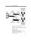
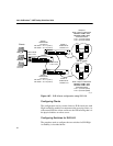
in the load balancing scheme. Without ESRP, another switch
interconnecting all the servers is necessary.
• One switch is designated as unit 1 and the other as unit 2. This
designation determines which VIPs are active on each switch in
the failover pair.
• In this configuration,
site1 is serviced by Switch 1 and has two
servers that respond to client requests.
Site2 is serviced by the
remote switch (Switch 2), and has two other servers that respond
to client requests.
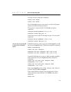
• If ping-check is enabled, it must not be directed at the remote
switch. The remote switch is checked by the High Availability
protocol. The ping-check works best when directed at a gateway
to ensure that a path out of the network is available to the switch.
• The configuration uses transparent mode and HTTP services, but
can be configured to support any of the currently supported load
balancing protocols.
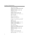
• The configurations for the High Availability switches are
identical, with the exception of the
failover command:
configure slb failover unit 1 remote 1.10.0.3
local 1.10.0.2 l4-port 1028
• The remote switch is set to unit 2, and the remote/local IP
addresses are reversed to accurately describe the network, as
shown in this command:
configure slb failover unit 2 remote 1.10.0.2
local 1.10.0.3 l4-port 1028
Web Server configuration
In the configuration shown in Figure 18.7 on page 388, basic HTTP,
configured at TCP port 80, is the only service being load balanced.
It is important that the services match those configured on the
switch. For example, HTTP services configured at TCP port 7080
on the switch would require the servers to be able to allow
connections at port 7080. You must also ensure that the SLB
configuration is valid before enabling High Availability.
All four servers (two local and two connected to the remote switch)
should be identical in content, with the content for both site1 and
site2 configured to be served.