C H A P T E R 2 Installation and Setup
19
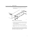
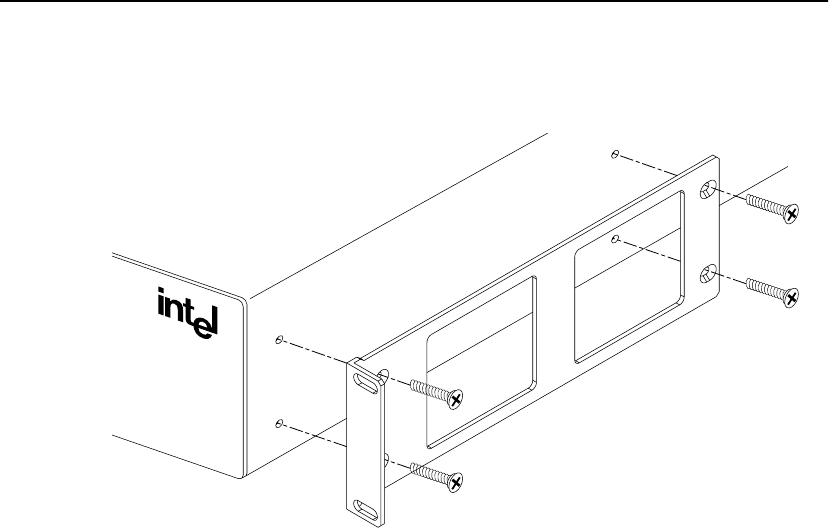
4 Replace the screws and fully tighten with a screwdriver, as
shown in Figure 2.1.
Figure 2.1: Fitting the mounting bracket
5 Repeat the two previous steps for the other side of the switch.
6 Insert the switch into the 19-inch rack. Ensure that ventilation
holes are not obstructed.
7 Secure the switch with rack mount screws (not provided).
8 Remove the label over the AC connector and attach the power
cord.
9 Attach the cables according to your own network configuration.
Many performance problems are caused by improper cabling. Pay
careful attention to distance and cable type restrictions. See “Media
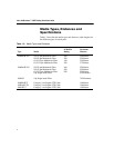
Types, Distances and Specifications” on page 14.
480t_028
®


