C H A P T E R 18 Server Load Balancing (SLB)
385
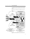
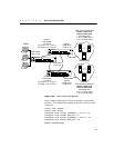
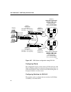
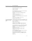
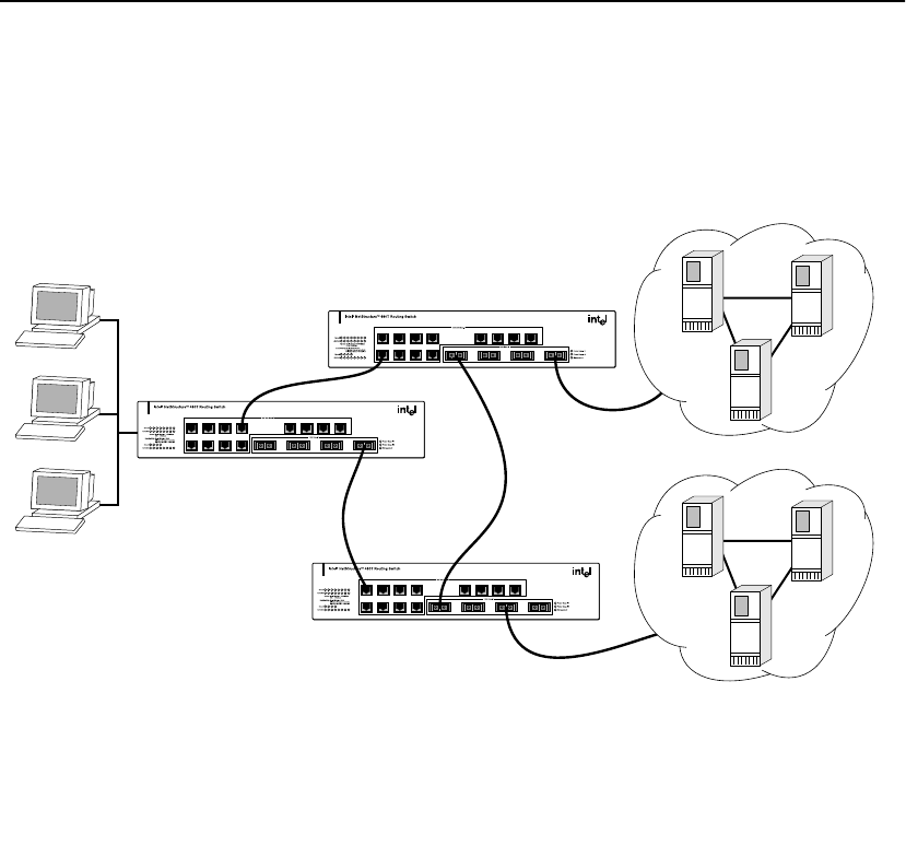
Figure 18.6: Active-active configuration
In this sample configuration, failover is enabled to ensure fault
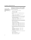
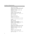
tolerance. To configure this example on the first switch, use these
commands:
create vlan inside
create vlan server
configure vlan inside ipaddress 1.10.0.2 /16
configure vlan inside add port 10
configure vlan server ipaddress 1.205.0.1 /16
configure vlan server add port 4-8
enable ipforwarding
3421
7865
11 12109
13 161514
87654321
161514131211109
Rx TxRx TxRx TxRx Tx
3421
7865
11 12109
13 161514
87654321
161514131211109
Rx TxRx TxRx TxRx Tx
3421
7865
11 12109
13 161514
87654321
161514131211109
Rx TxRx TxRx TxRx Tx
VLAN outside
1.201.0.1/16
Switch 1
VLAN inside
1.10.0.2/16
VIP site1 1.10.1.1 (unit 1)
VIP site2 1.10.1.2 (unit 2)
Switch 1
VLAN server
1.205.0.1/16
Switch 2
VLAN server
1.206.0.1/16
testpool2
Real unique IP addresses
Server1 1.206.1.1/16
Server2 1.206.1.2/16
Associated VIPs
1.10.1.1 port 80 (site1)
1.10.1.2 port 80 (site2)
test oo
Real unique IP addresses
Server1 1.205.1.1/16
Server2 1.205.1.2/16
Associated VIPs
1.10.1.1 port 80 (site1)
1.10.1.2 port 80 (site2)
Switch 2
VLAN inside
1.10.0.3/16
VIP site1 1.10.1.1 (unit 1)
VIP site2 1.10.1.2 (unit 2)
VLAN inside
1.10.0.1/16
Clients
Server pools


