2-116
Section 2 — Control Panel Descriptions
and the DPM, as described in the “Cable Connections” portion of
the Installation and Service manual.
NOTE:
The Effects Send feature requires that the Effects Send
Crosspoint module be installed in Cell 11 of Bay B in the switcher frame,
and that Aux Output modules be installed in the appropriate output cells
on the back of the switcher frame.
In addition, the following functions must be assigned, as
described in the “Startup Section” portion of the User Guide:
■ The DPM type, aux bus control, port assignment, and channel
routing must be set up in the DPM Setup menu
(config/extern_if/dpm_if_setup).
■ The appropriate aux buses must be assigned to the DPM in
the DPM Map Aux Buses menu
(config/extern_if/dpm_setup/dpm_map_aux_buses).
■ For effects looping, the aux bus return path must be mapped
in the DPM Map Inputs menu
(config/extern_if/dpm_if_setup/dpm_map_inputs).
■ If the output of the DPM is to be used as an input to the
switcher in non-looping mode, that input must be mapped as
for other primary inputs in the Map Inputs menu
(config/inputs/map_inputs).
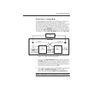
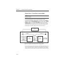
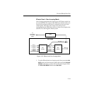
The Effects Send feature may be used either in Loop Mode or in
No Loop Mode, as described below. This selection is made in the
Aux Menu.


