


1-4
Section 1 — System Overview
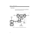
Physical Description
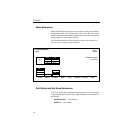
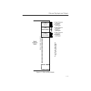
The switcher consists of three main areas: the Control Panel, the
Signal Processor Frame, and the Frame Power Supply (see
Figure 1-1). The electronic circuitry in the Model 3000 is primarily
contained on circuit boards and modules in the Signal Processor
Frame and Control Panel.
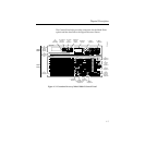
Signal Processor Frame
The Signal Processor Frame is a large rack-mounted unit that
houses the system controller, effects logic, video and key
processors, and input/output interfaces.
In addition to the basic system, a typical system may have several
options such as Chroma Keyers, Secondary Wipe Generator, and
Frame Store. Most options are available as circuit board modules
to be installed in the Signal Processor Frame.
Refer to the Model 3000 Installation and Service manual for a
complete description of the Signal Processor.
A main processor (HOS, or Head-Of-State) and separate
M/E processors reside within the Signal Processor Frame. Since
each M/E has its own processor, failure of one processor may not
disable the entire switcher. Individual effects can continue to
operate independently in a limited capacity.