101 www.national.com
CP3BT26
DTGL The DMA Toggle bit is used to determine the
initial state of Automatic DMA (ADMA) opera-
tions. Software initially sets this bit if starting
with a DATA1 operation, and clears this bit if
starting with a DATA0 operation. Writes to this
bit also update the NTGL bit in the DMAEV
register.
IGNRXTGL The Ignore RX Toggle controls whether the
compare between the NTGL bit in the DMAEV
register and the TOGGLE bit in the respective
RXSn register is ignored during receive oper-
ations. If the compare is ignored, a mismatch
of the bits during a receive operation does not
stop ADMA operation. If the compare is not ig-
nored, the ADMA stops in case of a mismatch
of the two toggle bits. After reset, this bit is
cleared.
0 – Compare toggle bits.
1 – Ignore toggle bits.
DEN The DMA Enable bit enables DMA mode. If
DMA mode is disabled and the current DMA
cycle has been completed (or was not yet is-
sued) the DMA transfer is terminated. This bit
is cleared after reset.
0 – DMA mode disabled.
1 – DMA mode enabled.
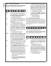
18.3.19 DMA Event Register (DMAEV)
The DMAEV register bits are used in ADMA mode. Bits 0 to
3 may cause an interrupt if not cleared, even if the device is
not set to ADMA mode. Until all of these bits are cleared,
ADMA mode cannot be initiated. Conversely, ADMA mode
is automatically terminated when any of these bits are set.
The DMAEV register provides access from the CPU bus as
described below. It is clear after reset.
DSHLT The DMA Software Halt bit is set when ADMA
operations have been halted by software. This
bit is set by the hardware only after the DMA
engine completes any necessary cleanup op-
erations and returns to Idle state.
The DSHLST bits provide read access and
can only be written with a 0 from the CPU bus.
After reset these bits are cleared.
0 – No software ADMA halt.
1 – ADMA operations have been halted by
software.
DERR The DMA Error bit is set to indicate that a
packet has not been received or transmitted
correctly. It is also set, if the TOGGLE bit in the
RXSx/TXSx register does not equal the NTGL
bit in the DMAEV register after packet recep-
tion/transmission. (Note that this comparison
is made before the NTGL bit changes state
due to packet transfer). For receiving, the
DERR bit is equivalent to the RX_ERR bit. For
transmitting, the DERR bit is equivalent to the
TX_DONE bit (set) and the ACK_STAT bit (not
set). If the AEH bit in the DMA Error Count
(DMAERR) register is set, the DERR bit is not
set until DMAERRCNT in the DMAERR regis-
ter is cleared, and another error is detected.
Errors are handled as specified in the DMAE-
RR register. The DERR bit provides read ac-
cess and can only be written with a 0 from the
CPU bus. After reset this bit is cleared.
0 – No DMA error occurred.
1 – DMA error occurred.
DCNT The DMA Count bit is set when the DMA
Count (DMACNT) register is 0 (see the
DMACNT register for more information). The
DCNT bit provides read access and can only
be written with a 0 from the CPU bus. After re-
set this bit is cleared.
0 – DMACNT register is not 0.
1 – DMACNT register is 0.
DSIZ The DMA Size bit is only significant for DMA
receive operations. It indicates, by being set,
that a packet has been received which is less
than the full length of the FIFO. This normally
indicates the end of a multi-packet transfer.
The DSIZ bit provides read access and can
only be written with a 0 from the CPU bus. Af-
ter reset this bit is cleared.
0 – No condition indicated.
1 – A packet has been received which is less
than the full length of the FIFO.
ARDY The Automatic DMA Ready bit is set when the
ADMA mode is ready and active. After setting
the DMACNTRL.ADMA bit and the active
USB transaction (if any) is finished and the
specified endpoint (DMACNTRL.DSRC) is
flushed, the USB node enters ADMA mode.
This bit is automatically cleared when the
ADMA mode is finished and the current DMA
operation is completed. After reset the ARDY
bit is cleared.
0 – ADMA mode not ready.
1 – ADMA mode ready and active.
NTGL The Next Toggle bit determines the toggle
state of the next data packet sent (if transmit-
ting), or the expected toggle state of the next
data packet (if receiving). This bit is initialized
by writing to the DTGL bit of the DMACNTRL
register. It then changes state with every
packet sent or received on the endpoint pres-
ently selected by DSRC[2:0]. If DTGL write
operation occurs simultaneously with the bit
update operation, the write takes precedence.
If transmitting, whenever ADMA operations
are in progress the DTGL bit overrides the
corresponding TOGGLE bit in the TXCx regis-
ter. In this way, the alternating data toggle oc-
curs correctly on the USB. Note that there is
no corresponding mask bit for this event be-
cause it is not used to generate interrupts.
The NTGL bit provides read-only access from
the CPU bus and is cleared after reset.
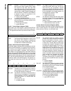
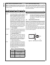
7 6 5 4 3 2 1 0
Reserved NTGL ARDY DSIZ DCNT DERR DSHLT


