www.national.com 18
CP3BT26
5.5 ADDRESSING MODES
The CR16C CPU core implements a load/store architec-
ture, in which arithmetic and logical instructions operate on
register operands. Memory operands are made accessible
in registers using load and store instructions. For efficient
implementation of I/O-intensive embedded applications, the
architecture also provides a set of bit operations that oper-
ate on memory operands.
The load and store instructions support these addressing
modes: register/pair, immediate, relative, absolute, and in-
dex addressing. When register pairs are used, the lower bits
are in the lower index register and the upper bits are in the
higher index register. When the CFG.SR bit is clear, the 32-
bit registers R12, R13, RA, and SP are also treated as reg-
ister pairs.
References to register pairs in assembly language use pa-
rentheses. With a register pair, the lower numbered register
pair must be on the right. For example,
jump (r5, r4)
load $4(r4,r3), (r6,r5)
load $5(r12), (r13)
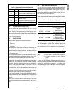
The instruction set supports the following addressing
modes:
For additional information on the addressing modes, see the
CompactRISC CR16C Programmer's Reference Manual.
Register/Pair
Mode
In register/pair mode, the operand is held
in a general-purpose register, or in a gen-
eral-purpose register pair. For example,
the following instruction adds the con-
tents of the low byte of register r1 to the
contents of the low byte of r2, and places
the result in the low byte register r2. The
high byte of register r2 is not modified.
ADDB R1, R2
Immediate
Mode
In immediate mode, the operand is a con-
stant value which is encoded in the in-
struction. For example, the following
instruction multiplies the value of r4 by 4
and places the result in r4.
MULW $4, R4
Relative Mode In relative mode, the operand is ad-
dressed using a relative value (displace-
ment) encoded in the instruction. This
displacement is relative to the current
Program Counter (PC), a general-pur-
pose register, or a register pair.
In branch instructions, the displacement
is always relative to the current value of
the PC Register. For example, the follow-
ing instruction causes an unconditional
branch to an address 10 ahead of the
current PC.
BR *+10
In another example, the operand resides
in memory. Its address is obtained by
adding a displacement encoded in the in-
struction to the contents of register r5.
The address calculation does not modify
the contents of register r5.
LOADW 12(R5), R6
The following example calculates the ad-
dress of a source operand by adding a
displacement of 4 to the contents of a
register pair (r5, r4) and loads this oper-
and into the register pair (r7, r6). r7 re-
ceives the high word of the operand, and
r6 receives the low word.
LOADD 4(r5, r4), (r7, r6)
Index Mode In index mode, the operand address is
calculated with a base address held in ei-
ther R12 or R13. The CFG.SR bit must
be clear to use this mode.
For relative mode operands, the mem-
ory address is calculated by adding
the value of a register pair and a dis-
placement to the base address. The
displacement can be a 14 or 20-bit un-
signed value, which is encoded in the
instruction.
For absolute mode operands, the
memory address is calculated by add-
ing a 20-bit absolute address encoded
in the instruction to the base address.
In the following example, the operand ad-
dress is the sum of the displacement 4,
the contents of the register pair (r5,r4),
and the base address held in register r12.
The word at this address is loaded into
register r6.
LOADW [r12]4(r5, r4), r6
Absolute Mode In absolute mode, the operand is located
in memory, and its address is encoded in
the instruction (normally 20 or 24 bits).
For example, the following instruction
loads the byte at address 4000 into the
lower 8 bits of register r6.
LOADB 4000, r6


