www.national.com 110
CP3BT26
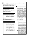
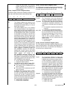
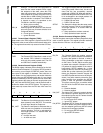
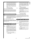
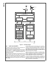
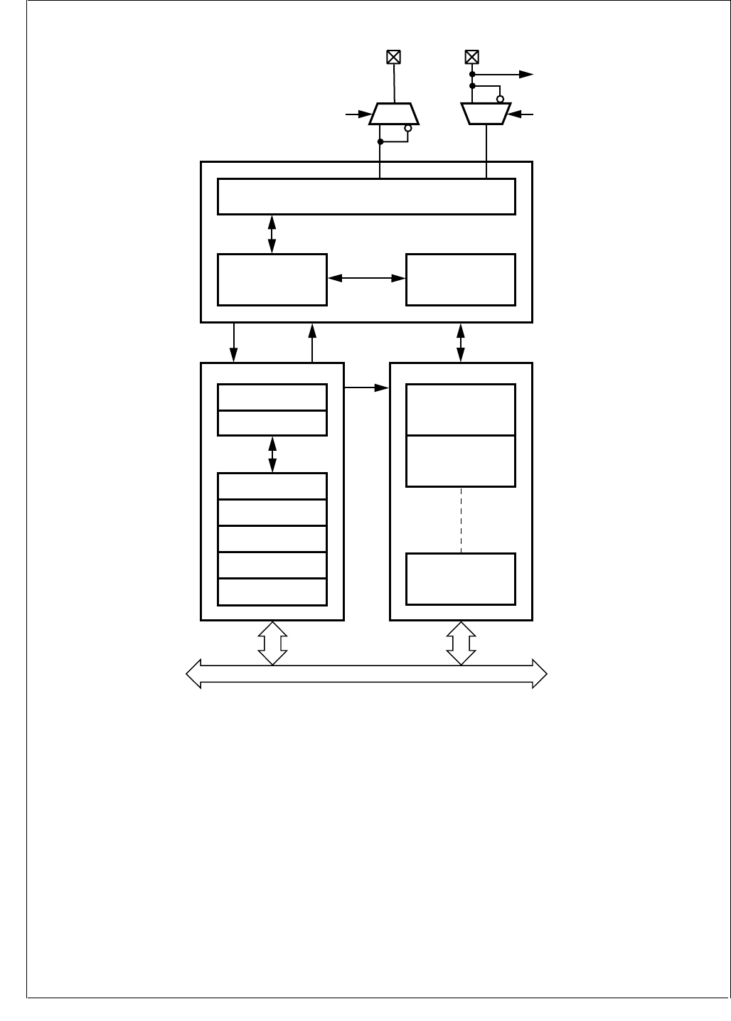
Figure 34. CAN Block Diagram
19.2 BASIC CAN CONCEPTS
This section provides a generic overview of the basic con-
cepts of the Controller Area Network (CAN).
The CAN protocol is a message-based protocol that allows
a total of 2032 (2
11
- 16)
different messages in the standard
format and 512 million (2
29
- 16) different messages in the
extended frame format.
Every CAN Frame is broadcast on the common bus. Each
module receives every frame and filters out the frames
which are not required for the module's task. For example,
if a dashboard sends a request to switch on headlights, the
CAN module responsible for brake lights must not process
this message.
A CAN master module has the ability to set a specific bit
called the “remote data request bit” (RTR) in a frame. Such
a message is also called a “Remote Frame”. It causes an-
other module, either another master or a slave which ac-
cepts this remote frame, to transmit a data frame after the
remote frame has been completed.
Additional modules can be added to an existing network
without a configuration change. These modules can either
perform completely new functions requiring new data, or
process existing data to perform a new functionality.
As the CAN network is message oriented, a message can
be used as a variable which is automatically updated by the
controlling processor. If any module cannot process infor-
mation, it can send an overload frame.
CPU BUS
Transceiver Logic
BTL, RX shift, TX shift, CRC
CAN CORE
INTERFACE MANAGEMENT RAM
Bit Stream Processor Error Management Logic
Interface Management
Processor
Acceptance Filtering
Interface Management
Processor
ACCEPTANCE
MASKS
CONTROL
CAN PRESCALER
BTL CONFIG
TX/RX
Message Buffer 0
TX/RX
Message Buffer 1
TX/RX
Message Buffer 14
CANRX
Wake-Up
CRX
Control
Status
Control
Data
1
0
CANTX
CTX
1
0
DS018


