57 www.national.com
CP3BT26
12.3 IDLE MODE
In Idle mode, the System Clock is disabled and therefore the
clock is stopped to most modules of the device. The PLL
and the high-frequency oscillator may be disabled as con-
trolled by register bits. The low-frequency oscillator remains
active. The Power Management Module (PMM) and the
Timing and Watchdog Module (TWM) continue to operate
off the Slow Clock. Auxiliary Clocks 1 and 2 can be turned
off under software control before switching to a power sav-
ing mode, or they remain active as long as Main Clock is
also active. Alternatively, the 12 MHz Main Clock and the
PLL can also be controlled by the Hardware Clock Control
function, if enabled.
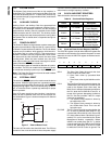
The Bluetooth LLC can either be switched to the Slow Clock
internally in the module or it remains running off the Auxilia-
ry Clock 1 as long as the Main Clock and Auxiliary Clock 1
are enabled.
12.4 HALT MODE
In Halt mode, all the device clocks, including the System
Clock, Main Clock, and Slow Clock, are disabled. The high-
frequency oscillator and PLL are turned off. The low-fre-
quency oscillator continues to operate, however its circuitry
is optimized to guarantee lowest possible power consump-
tion. This mode allows the device to reach the absolute min-
imum power consumption without losing its state (memory,
registers, etc.).
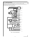
12.5 HARDWARE CLOCK CONTROL
The Hardware Clock Control (HCC) mechanism gives the
Bluetooth Lower Link Controller (LLC) individual control
over the high-frequency oscillator and the PLL. The Blue-
tooth LLC can enter a Sleep mode for a specified number of
low-frequency clock cycles. While the Bluetooth LLC is in
Sleep mode and the CP3BT26 is in Power Save or Idle
mode, the HCC mechanism may be used to control whether
the high-frequency oscillator, PLL, or both units are dis-
abled.
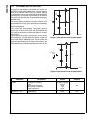
Altogether, three mechanisms control whether the high-fre-
quency oscillator is active, and four mechanisms control
whether the PLL is active:
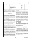
HCC Bits: The HCCM and HCCH bits in the PMMCR
register may be used to disable the high-frequency oscil-
lator and PLL, respectively, in Power Save and Idle
modes when the Bluetooth LLC is in Sleep mode.
Disable Bits: The DMC and DHC bits in the PMMCR
register may be used to disable the high-frequency oscil-
lator and PLL, respectively, in Power Save and Idle
modes. When used to disable the high-frequency oscilla-
tor or PLL, the DMC and DHC bits override the HCC
mechanism.
Power Management Mode: Halt mode disables the
high-frequency oscillator and PLL. Active Mode enables
them. The DMC and DHC bits and the HCC mechanism
have no effect in Active or Halt mode.
PLL Power Down Bit: The PLLPWD bit in the CRCTRL
register can be used to disable the PLL in all modes. This
bit does not affect the high-frequency oscillator.
12.6 POWER MANAGEMENT REGISTERS
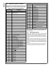
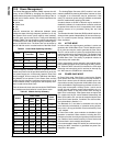
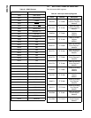
Table 26 lists the power management registers.
12.6.1 Power Management Control Register (PMMCR)
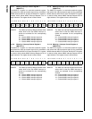
The Power Management Control/Status Register (PMMCR)
is a byte-wide, read/write register that controls the operating
power mode (Active, Power Save, Idle, or Halt) and enables
or disables the high-frequency oscillator in the Power Save
and Idle modes. At reset, the non-reserved bits of this reg-
ister are cleared. The format of the register is shown below.
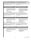
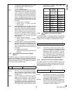
PSM If the Power Save Mode bit is clear and the
WBPSM bit is clear, writing 1 to the PSM bit
causes the device to start the switch to Power
Save mode. If the WBPSM bit is set when the
PSM bit is written with 1, entry into Power
Save mode is delayed until execution of a
WAIT instruction. The PSM bit becomes set
after the switch to Power Save mode is com-
plete. The PSM bit can be cleared by soft-
ware, and it can be cleared by hardware when
a hardware wake-up event is detected.
0
– Device is not in Power Save mode.
1 – Device is in Power Save mode.
IDLE The Idle Mode bit indicates whether the de-
vice has entered Idle mode. The WBPSM bit
must be set to enter Idle mode. When the
IDLE bit is written with 1, the device enters
IDLE mode at the execution of the next WAIT
instruction. The IDLE bit can be set and
cleared by software. It is also cleared by the
hardware when a hardware wake-up event is
detected.
0
– Device is not in Idle mode.
1
– Device is in Idle mode.
Table 26 Power Management Registers
Name Address Description
PMMCR FF FC60h
Power Management
Control Register
PMMSR FF FC62h
Power Management
Status Register
7 6 5 4 3 2 1 0
HCCH HCCM DHC DMC WBPSM HALT IDLE PSM


