189 www.national.com
CP3BT26
24.3.7 ACB Own Address Register 1 (ACBADDR1)
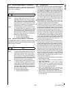
The ACBADDR1 register is a byte-wide, read/write register
that holds the module’s first ACCESS.bus address. After re-
set, its value is undefined.
ADDR The Own Address field holds the first 7-bit AC-
CESS.bus address of this device. When in
slave mode, the first 7 bits received after a
Start Condition are compared to this field (first
bit received to bit 6, and the last to bit 0). If the
address field matches the received data and
the SAEN bit is set, a match is detected.
SAEN The Slave Address Enable bit controls wheth-
er address matching is performed in slave
mode. When set, the SAEN bit indicates that
the ADDR field holds a valid address and en-
ables the match of ADDR to an incoming ad-
dress byte. When cleared, the ACB does not
check for an address match.
0 – Address matching disabled.
1 – Address matching enabled0.
24.3.8 ACB Own Address Register 2 (ACBADDR2)
The ACBADDR2 register is a byte-wide, read/write register
that holds the module’s second ACCESS.bus address. After
reset, its value is undefined.
ADDR The Own Address field holds the second 7-bit
ACCESS.bus address of this device. When in
slave mode, the first 7 bits received after a
Start Condition are compared to this field (first
bit received to bit 6, and the last to bit 0). If the
address field matches the received data and
the SAEN bit is set, a match is detected.
SAEN The Slave Address Enable bit controls wheth-
er address matching is performed in slave
mode. When set, the SAEN bit indicates that
the ADDR field holds a valid address and en-
ables the match of ADDR to an incoming ad-
dress byte. When cleared, the ACB does not
check for an address match.
0 – Address matching disabled.
1 – Address matching enabled.
24.4 USAGE HINTS
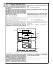
When the ACB module is disabled, the ACBCST.BB bit is
cleared. After enabling the ACB (ACBCTL2.ENABLE =
1) in systems with more than one master, the bus may be
in the middle of a transaction with another device, which
is not reflected in the BB bit. There is a need to allow the
ACB to synchronize to the bus activity status before issu-
ing a request to become the bus master, to prevent bus
errors. Therefore, before issuing a request to become the
bus master for the first time, software should check that
there is no activity on the bus by checking the BB bit after
the bus allowed time-out period.
When waking up from power down, before checking the
ACBCST.MATCH bit, test the ACBCST.BUSY bit to make
sure that the address transaction has finished.
The BB bit is intended to solve a deadlock in which two,
or more, devices detect a usage conflict on the bus and
both devices cease being bus masters at the same time.
In this situation, the BB bits of both devices are active
(because each deduces that there is another master cur-
rently performing a transaction, while in fact no device is
executing a transaction), and the bus would stay locked
until some device sends a ACBCTL1.STOP condition.
The ACBCST.BB bit allows software to monitor bus us-
age, so it can avoid sending a STOP signal in the middle
of the transaction of some other device on the bus. This
bit detects whether the bus remains unused over a cer-
tain period, while the BB bit is set.
In some cases, the bus may get stuck with the SCL or
SDA lines active. A possible cause is an erroneous Start
or Stop Condition that occurs in the middle of a slave re-
ceive session. When the SCL signal is stuck active, there
is nothing that can be done, and it is the responsibility of
the module that holds the bus to release it. When the
SDA signal is stuck active, the ACB module enables the
release of the bus by using the following sequence. Note
that in normal cases, the SCL signal may be toggled only
by the bus master. This protocol is a recovery scheme
which is an exception that should be used only in the
case when there is no other master on the bus. The re-
covery scheme is as follows:
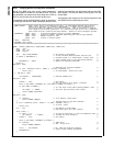
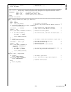
1. Disable and re-enable the module to set it into the not
addressed slave mode.
2. Set the ACBCTL1.START bit to make an attempt to
issue a Start Condition.
3. Check if the SDA signal is active (low) by reading
ACBCST.TSDA bit. If it is active, issue a single SCL
cycle by writing 1 to ACBCST.TGSCL bit. If the SDA
line is not active, continue from step 5.
4. Check if the ACBST.MASTER bit is set, which indi-
cates that the Start Condition was sent. If not, repeat
step 3 and 4 until the SDA signal is released.
5. Clear the BB bit. This enables the START bit to be ex-
ecuted. Continue according to “Bus Idle Error Recov-
ery” on page 184.
7 6 0
SAEN ADDR
7 6 0
SAEN ADDR


