www.national.com 76
CP3BT26
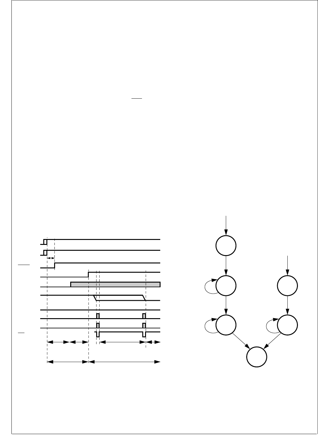
15.3 LMX5251 POWER-UP SEQUENCE
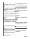
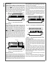
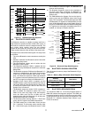
To power-up a Bluetooth system based on the CP3BT26
and LMX5251 devices, the following sequence must be per-
formed:
1. Apply VDD to the LMX5251.
2. Apply IOVCC and VCC to the CP3BT26.
3. Drive the RESET# pin of the LMX5251 high a minimum
of 2 ms after the LMX5251 and CP3000 supply rails are
powered up. This resets the LMX5251 and CP3BT26.
4. After internal Power-On Reset (POR) of the CP3BT26,
the RFDATA pin is driven high. The RFCE, RFSYNC,
and SDAT pins are in TRI-STATE mode. Internal pull-
up/pull-down resistors on the CCB_CLOCK (SCLK),
CCB_DATA (SDAT), CCB_LATCH (SLE
), and
TX_RX_SYNC (RFSYNC) inputs of the LMX5251 pull
these signals to states required during the power-up
sequence.
5. When the RFDATA pin is driven high, the LMX5251 en-
ables its oscillator. After an oscillator start-up delay, the
LMX5251 drives a stable 12-MHz BBP_CLOCK
(BBCLK) to the CP3BT26.
6. The Bluetooth baseband processor on the CP3BT26
now directly controls the RF interface pins and drives
the logic levels required during the power-up phase.
When the RFCE pin is driven high, the LMX5251
switches from “power-up” to “normal” mode and dis-
ables the internal pull-up/pull-down resistors on its RF
interface inputs.
7. In “normal” mode, the oscillator of the LMX5251 is con-
trolled by the RFCE signal. Driving RFCE high enables
the oscillator, and the LMX5251 drives its BBP_CLOCK
(BBCLK) output.
Figure 20. LMX5251 Power-Up Sequence
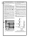
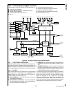
15.4 LMX5252 POWER-UP SEQUENCE
A Bluetooth system based on the CP3BT26 and LMX5252
devices has the following states:
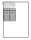
Off—When the LMX5252 enters Off mode, all configura-
tion data is lost. In this state, the LMX5252 drives BPOR
low.
Power-Up—When the power supply is on and the
LMX5252 RESET# input is high, the LMX5252 starts up
its crystal oscillator and enters Power-Up mode. After the
crystal oscillator is settled, the LMX5252 sends four
clock cycles on BRCLK (BBCLK) before driving BPOR
high.
RF Init—The baseband controller on the CP3BT26 now
drives RFCE high and takes control of the crystal oscilla-
tor. The baseband performs all the needed initialization
(such as writing the registers in the LMX5252 and crystal
oscillator trim).
Idle—The baseband controller on the CP3BT26 drives
RFDATA low when the initialization is ready. The
LMX5252 is now ready to start transmitting, receiving, or
enter Sleep mode.
Sleep—The LMX5252 can be forced into Sleep mode at
any time by driving RFCE low. All configuration settings
are kept, only the Bluetooth low power clock is running
(B3k2).
Wait XTL—When RFCE goes high, the crystal oscillator
becomes operational. When it is stable, the LMX5252
enters Idle mode and drives BRCLK (BBCLK).
Figure 21. LMX5252 Power States
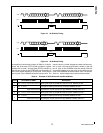
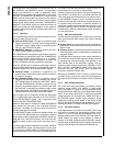
The power-up sequence for a Bluetooth system based on
the CP3BT26 and LMX5252 devices is shown in Figure 22.
VDD
LMX5251
RFCE
BBCLK
RFDATA
RFSYNC
VCC
CP3000
IOVCC
CP3000
Low
Low
High
Low
SDAT
Low
SCLK
Low
SLE
Standby
LMX5251 in Normal ModeLMX5251 in
Power-Up Mode
LMX5251
Oscillator
Start-Up
LMX5251
Initialization
CP3000
Initialization
Active
High
DS016
RESET#
LMX5251
RESET
CP3000
t
PTOR
Idle
DS324
Crystal Osc. Stable
RF Init
RFCE = High
RFDATA = Don't Care
Write Registers
RESET# = High and
Power is On
Power-Up
Wait for
Crystal Osc.
To Stabilize
RESET# = Low or
Power is cycled
Off
RFCE = High
Wait XTL
Wait for
Crystal Osc.
To Stabilize
RFCE = Low
Sleep
Any State
Any State
After RF Init
Crystal Osc. Stable


