www.national.com 148
CP3BT26
20.5.6 Network Mode
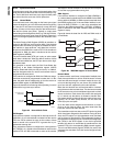
In network mode, each frame sync signal marks the begin-
ning of new frame. Each frame can consist of up to four
slots. The audio interface operates in a similar way to nor-
mal mode, however, in network mode the transmitter and re-
ceiver can be assigned to specific slots within each frame as
described below.
20.5.7 Transmit
The transmitter only shifts out data during the assigned slot.
During all other slots the STD output is in TRI-STATE mode.
DMA Operation
When a complete data word has been transmitted through
the STD pin, a new data word is reloaded from the corre-
sponding transmit DMA register n (ATDRn). A DMA request
is asserted when ATDRn is empty. If a new data word must
be transmitted in a slot n while ATDRn is still empty, the pre-
vious slot n data will be retransmitted.
FIFO Operation
When a complete data word has been transmitted through
the STD pin, a new data word is reloaded from the transmit
FIFO from the current location of the Transmit FIFO Read
Pointer (TRP). After that, the TRP is automatically incre-
mented by 1. Therefore, the audio data to be transmitted in
the next slot of the frame is read from the next FIFO loca-
tion.
A write to the Audio Transmit FIFO Register (ATFR) results
in a write to the transmit FIFO at the current location of the
Transmit FIFO Write Pointer (TWP). After every write oper-
ation to the transmit FIFO, the TWP is automatically incre-
mented by 1.
When the TRP is equal to the TWP and the last access to
the FIFO was a read operation (transfer to the ATSR), the
transmit FIFO is empty. When an additional read operation
from the FIFO to the ATSR is performed (while the FIFO is
already empty), a transmit FIFO underrun occurs. In this
case, the read pointer (TRP) will be decremented by 1 (in-
cremented by 15) and the previous data word will be trans-
mitted again. A transmit FIFO underrun is indicated by the
TXU bit in the Audio Interface Transmit Status and Control
Register (ATSCR). No transmit interrupt will be generated
(even if enabled).
If the current TRP is equal to the TWP and the last access
to the FIFO was a write operation (to the ATFR), the FIFO is
full. If an additional write to the ATFR is performed, a trans-
mit FIFO overrun occurs. This error condition is not prevent-
ed by hardware. Software must ensure that no transmit
overrun occurs.
The transmit frame synchronization pulse on the SFS pin
and the transmit shift clock on the SCK pin may be generat-
ed internally, or they can be supplied by an external source.
20.5.8 Receive
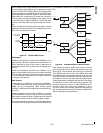
The receive shift register (ARSR) receives data words of all
slots in the frame, regardless of the slot assignment of the
interface. However, only those ARSR contents are trans-
ferred to the receive FIFO or DMA receive register which
were received during the assigned time slots. A receive in-
terrupt or DMA request is initiated when this occurs.
DMA Operation
When a complete data word has been received through the
SRD pin in a slot n, the new data word is transferred to the
corresponding receive DMA register n (ARDRn). A DMA re-
quest is asserted when the ARDRn register is full. If a new
slot n data word is received while the ARDRn register is still
full, the ARDRn register will be overwritten with the new da-
ta.
FIFO Operation
When a complete word has been received, it is transferred
to the receive FIFO at the current location of the Receive
FIFO Write Pointer (RWP). After that, the RWP is automati-
cally incremented by 1. Therefore, data received in the next
slot is copied to the next higher FIFO location.
A read from the Audio Receive FIFO Register (ARFR) re-
sults in a read from the receive FIFO at the current location
of the Receive FIFO Read Pointer (RRP). After every read
operation from the receive FIFO, the RRP is automatically
incremented by 1.
When the RRP is equal to the RWP and the last access to
the FIFO was a transfer to the ARFR, the receive FIFO is
full. When a new complete data word has been shifted into
the ARSR while the receive FIFO was already full, the shift
register overruns. In this case, the new data in the ARSR will
not be transferred to the FIFO and the RWP will not be in-
cremented. A receive FIFO overrun is indicated by the RXO
bit in the Audio Interface Receive Status and Control Regis-
ter (ARSCR). No receive interrupt will be generated (even if
enabled).
When the current RWP is equal to the TWP and the last ac-
cess to the receive FIFO was a read from ARFR, a receive
FIFO underrun has occurred. This error condition is not pre-
vented by hardware. Software must ensure that no receive
underrun occurs.
The receive frame synchronization pulse on the SRFS pin
(or SFS in synchronous mode) and the receive shift clock on
the SRCLK (or SCK in synchronous mode) may be gener-
ated internally, or they can be supplied by an external
source.
20.6 COMMUNICATION OPTIONS
20.6.1 Data Word Length
The word length of the audio data can be selected to be ei-
ther 8 or 16 bits. In 16-bit mode, all 16 bits of the transmit
and receive shift registers (ATSR and ARSR) are used. In 8-
bit mode, only the lower 8 bits of the transmit and receive
shift registers (ATSR and ARSR) are used.
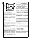
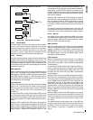
20.6.2 Frame Sync Signal
The audio interface can be configured to use either long or
short frame sync signals to mark the beginning of a new
data frame. If the corresponding Frame Sync Select (FSS)
bit in the Audio Control and Status register is clear, the re-
ceive and/or transmit path generates or recognizes short
frame sync pulses with a length of one bit shift clock period.
When these short frame sync pulses are used, the transfer
of the first data bit or the first slot begins at the first positive
edge of the shift clock after the negative edge on the frame
sync pulse.


