111 www.national.com
CP3BT26
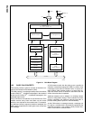
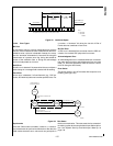
The CAN protocol allows several transmitting modules to
start a transmission at the same time as soon as they detect
the bus is idle. During the start of transmission, every node
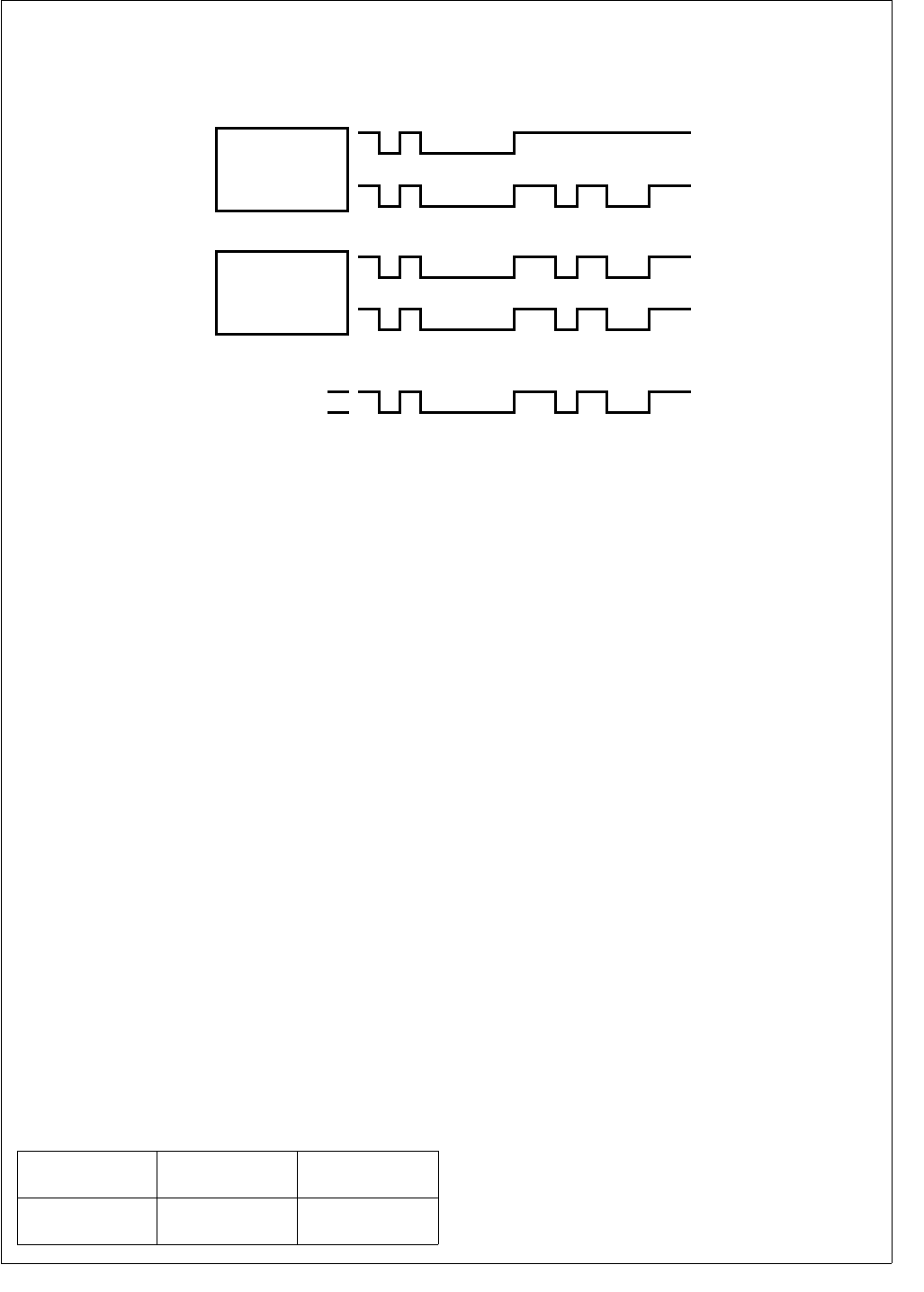
monitors the bus line to detect whether its message is over-
written by a message with a higher priority. As soon as a
transmitting module detects another module with a higher
priority accessing the bus, it stops transmitting its own frame
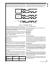
and switches to receive mode, as shown in Figure 35.
Figure 35. CAN Message Arbitration
If a data or remote frame loses arbitration on the bus due to
a higher-prioritized data or remote frame, or if it is destroyed
by an error frame, the transmitting module will automatically
retransmit it until the transmission is successful or software
has canceled the transmit request.
If a transmitted message loses arbitration, the CAN module
will restart transmission at the next possible time with the
message which has the highest internal transmit priority.
19.2.1 CAN Frame Types
Communication via the CAN bus is basically established by
means of four different frame types:
Data Frame
Remote Frame
Error Frame
Overload Frame
Data and remote frames can be used in both standard and
extended frame format. If no message is being transmitted,
i.e., the bus is idle, the bus is kept at the “recessive” level.
Remote and data frames are non-return to zero (NRZ) cod-
ed with bit-stuffing in every bit field, which holds computable
information for the interface, i.e., start of frame, arbitration
field, control field, data field (if present), and CRC field.
Error and overload frames are also NRZ coded, but without
bit-stuffing.
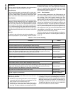
After five consecutive bits of the same value (including in-
serted stuff bits), a stuff bit of the inverted value is inserted
into the bit stream by the transmitter and deleted by the re-
ceiver. The following shows the stuffed and destuffed bit
stream for consecutive ones and zeros.
19.2.2 CAN Frame Fields
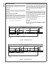
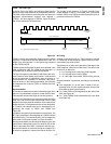
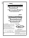
Data and remote frames consist of the following bit fields:
Start of Frame (SOF)
Arbitration Field
Control Field
Data Field
CRC Field
ACK Field
EOF Field
Start of Frame (SOF)
The Start of Frame (SOF) indicates the beginning of data
and remote frames. It consists of a single “dominant” bit. A
node is only allowed to start transmission when the bus is
idle. All nodes have to synchronize to the leading edge (first
edge after the bus was idle) caused by the SOF of the node
which starts transmission first.
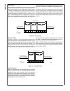
Arbitration Field
The Arbitration field consists of the identifier field and the
RTR (Remote Transmission Request) bit. For extended
frames there is also a SRR (Substitute Remote Request)
and a IDE (ID Extension) bit inserted between ID18 and
ID17 of the identifier field. The value of the RTR bit is “dom-
inant” in a data frame and “recessive” in a remote frame.
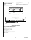
Control Field
The Control field consists of six bits. For standard frames it
starts with the ID Extension bit (IDE) and a reserved bit
(RB0). For extended frames, the control field starts with two
reserved bits (RB1, RB0). These bits are followed by the 4-
bit Data Length Code (DLC).
The CAN receiver accepts all possible combinations of the
reserved bits (RB1, RB0). The transmitter must be config-
ured to send only zeros.
TxPIN
RxPIN
MODULE A
TxPIN
RECESSIVE
DOMINANT
MODULE A SUSPENDS TRANSMISSION
BUS LINE
RxPIN
MODULE B
DS019
Original or
unstuffed bit stream
10000011111 . . . 01111100000 . . .
Stuffed bit stream
(stuff bits in bold)
1000001111101 . . . 0111110000010 . . .


