www.national.com 128
CP3BT26
19.10 CAN CONTROLLER REGISTERS
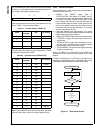
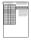
Table 51 lists the CAN module registers.
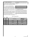
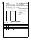
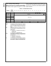
19.10.1 Buffer Status/Control Register (CNSTAT)
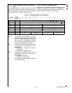
The buffer status (ST), the buffer priority (PRI), and the data
length code (DLC) are controlled by manipulating the con-
tents of the Buffer Status/Control Register (CNSTAT). The
CPU and CAN module have access to this register.
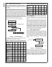
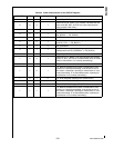
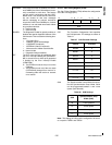
ST The Buffer Status field contains the status in-
formation of the buffer as shown in Table 52.
This field can be modified by the CAN module.
The ST0 bits acts as a buffer busy indication.
When the BUSY bit is set, any write access to
the buffer is disabled with the exception of the
lower byte of the CNSTAT register. The CAN
module sets this bit if the buffer data is cur-
rently copied from the hidden buffer or if a
message is scheduled for transmission or is
currently transmitting. The CAN module al-
ways clears this bit on a status update.
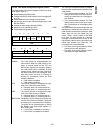
Table 51 CAN Controller Registers
Name Address Description
CNSTAT
See
Table 50.
CAN Buffer Status/
Control Register
CGCR 0E F100h
CAN Global
Configuration Register
CTIM 0E F102h CAN Timing Register
GMSKX 0E F104h Global Mask Register
GMSKB 0E F106h Global Mask Register
BMSKX 0E F108h Basic Mask Register
BMSKB 0E F10Ah Basic Mask Register
CIEN 0E F10Ch
CAN Interrupt
Enable Register
CIPND 0E F10Eh
CAN Interrupt
Pending Register
CICLR 0E F110h
CAN Interrupt
Clear Register
CICEN 0E F112h
CAN Interrupt Code
Enable Register
CSTPND 0E F114h
CAN Status
Pending Register
CANEC 0E F116h
CAN Error
Counter Register
CEDIAG 0E F118h
CAN Error
Diagnostic Register
CTMR 0E F11Ah CAN Timer Register
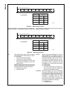
15 12 11 8 7 4 3 0
DLC Reserved PRI ST
0
R/W


