263 www.national.com
CP3BT26
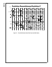
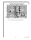
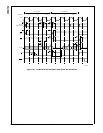
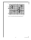
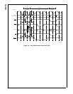
30.16 EXTERNAL BUS TIMING
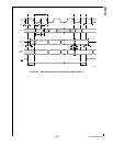
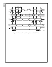
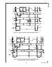
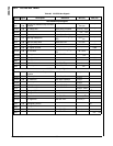
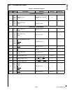
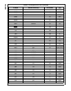
Table 93 External Bus Signals
Symbol
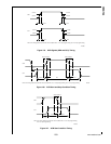
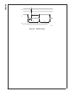
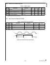
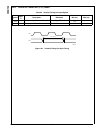
Figure
Description Reference Min (ns) Max (ns)
External Bus Input Signals
t
1
131,
133,
134,
135
Input Setup Time
D[15:0]
Before Rising Edge (RE)
on CLK
8
t
2
131,
133,
134,
135
Output Hold Time
D[15:0]
After RE on CLK 0
External Bus Output Signals
t
3
131,
132
Output Valid Time
D[15:0]
After RE on CLK 8
t
4
131,
132,
133,
134,
135
Output Valid Time
A[22:0]
After RE on CLK 8
t
5
131,
132,
133,
134,
135
Output Active/Inactive Time
RD
SEL[1:0]
SELIO
After RE on CLK 8
t
6
131,
132
Output Active/Inactive Time
WR[1:0]
After RE on CLK 0.5 Tclk + 8
t
7
133
Minimum Inactive Time
RD
At 2.0V Tclk - 4
t
8
131
Output Float Time
D[15:0]
After RE on CLK 8
t
9
131 Minimum Delay Time
From RD
Trailing Edge
(TE) to D[15:0] driven
Tclk - 4
t
10
131,
132
Minimum Delay Time
From RD
TE to SELn
Leading Edge (LE)
0
t
11
132 Minimum Delay Time From SELx TE to SELy LE 0
t
12
131,
132,
133,
134,
135
Output Hold Time
A[22:0]
D[15:0]
RD
SEL[2:0]
SELIO
After RE on CLK 0
t
13
131,
132
Output Hold Time
WR[1:0]
After RE on CLK 0.5 Tclk - 3


